
Electrostatic-to-pneumatic converter

An air pressure conversion and converter technology, which is applied in physical quantity changers, fluid pressure actuation devices, valve details, etc. It can solve the problem of not being able to change the pressure at the outlet, and achieve good vibration resistance, acceleration insensitivity, and stable response. The effect of improving sexuality, improving response performance and stabilizing response

Active Publication Date: 2020-09-08
SAMSON AG
View PDF1 Cites 0 Cited by
  • Summary
  • Abstract
  • Description
  • Claims
  • Application Information

AI Technical Summary

Problems solved by technology

Such an on-off valve therefore cannot change the pressure at the outlet

Method used


Image

  • Electrostatic-to-pneumatic converter
  • Electrostatic-to-pneumatic converter
  • Electrostatic-to-pneumatic converter

Examples


Embodiment Construction

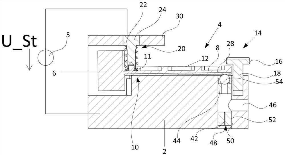
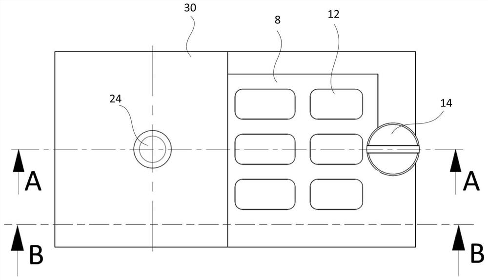
[0059] figure 1 shows along the figure 2 A cross-sectional view of the line A-A, figure 2 shows the basis figure 1 A top view of the electrostatic-pneumatic converter. according to figure 1 The electrostatic-pneumatic converter thus comprises an electrostatic control device comprising a ground electrode 2 and a control electrode 4 designed to be electrically insulated from the ground electrode 2 in the form of a movable equal-arm balance bar, the control electrode being grounded by a current source 5 The control voltage U_St between electrode 2 and control electrode 4 is activated. The control electrode 4 and the ground electrode 2 at least partially form a gap 3, the size of the gap can be changed according to the control voltage U_St applied between the control electrode 4 and the ground electrode 2, where the output pressure Pa is output as the air pressure at the outlet 46 The signal can be controlled depending on the control voltage U_St.

[0060] The ground elect...


PUM


Abstract

The invention relates to an electrostatic-pneumatic converter, comprising an electrostatic control device which comprises a ground electrode (2) and a control electrode (4), which is designed as a movable rocker and is electrically isolated from the earth electrode (2), which is connected between the earth electrode (2) and the control electrode (24), and valve means (40) having an inlet (42) forsupply of pressurized fluid (Pv), an outlet nozzle (44) in fluid communication with the inlet (42). and an output (46) in fluid communication with the input (42), the control electrode (4) at least partially forming a gap (3) with the ground electrode (2) whose gap size is dependent on that between the control electrode (4) and the ground electrode (2) of a current source (5) applied control voltage (U_St) is variable, wherein the gap size of the opening cross section of the output nozzle (4) is influenced, wherein the output pressure (Pa) as a pneumatic output signal at the output (46) depending on the control voltage (U_St) is controllable.

Description

technical field [0001] The invention relates to an electrostatic-pneumatic converter for converting a control voltage into a pneumatic output signal. Background technique [0002] DE10047705U1 discloses a microvalve for controlling fluid flow, which has at least one spool part, for the operation of the spool part, a drive mechanism based on the principle of electrostatic operation is provided, where the drive mechanism comprises at least one so-called Combined transmission drive mechanism. The spool part of the microvalve is rotatably mounted on a support point in the manner of a Wippe and is prestressed towards the initial position by means of a spring mechanism. Depending on the length of the equilibrator, one of the two outlets is closed and the other of the two outlets is opened. Such switching valves are therefore unable to change the pressure at the outlet. Contents of the invention [0003] The present invention is therefore based on the task of providing an elec...

Claims


Application Information

Patent Timeline
IPC IPC(8): F15B13/043F16K31/02
CPCF15B13/043F16K31/02F15B5/006
Inventor S·科尔本施拉格
Owner SAMSON AG
Learn More