Rapid locking device and foldable assisting box
A locking device and locking technology, applied in the field of mechanical accessories, can solve the problems of inconvenient luggage or scooters, the volume cannot be reduced to a minimum, and the disassembly cannot be carried out, so as to achieve convenient disassembly and assembly operations, and enhance fast assembly and locking. , Enhance the effect of rapid dismantling and separation
- Summary
- Abstract
- Description
- Claims
- Application Information
AI Technical Summary
Problems solved by technology
Method used
Image
Examples
Embodiment 1
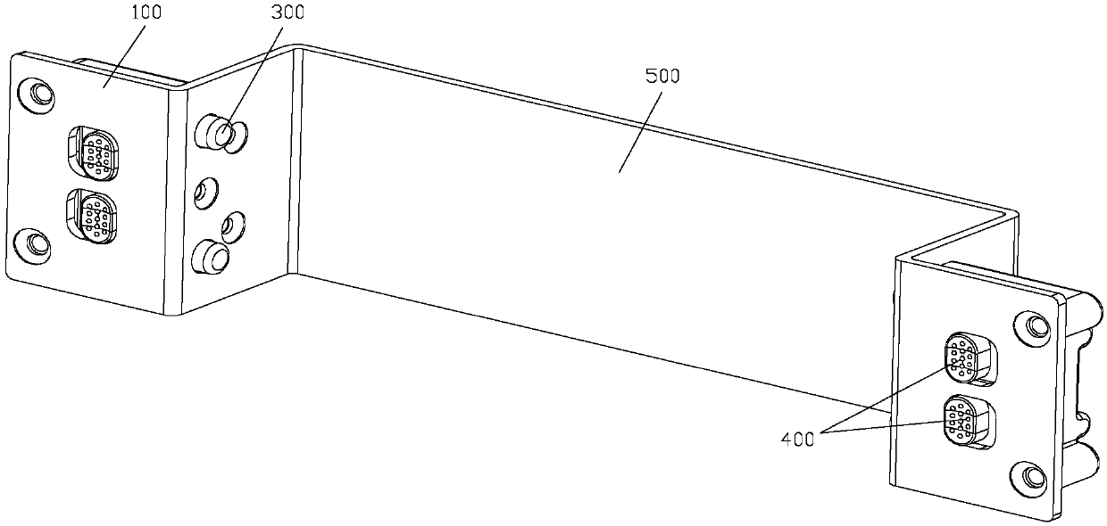
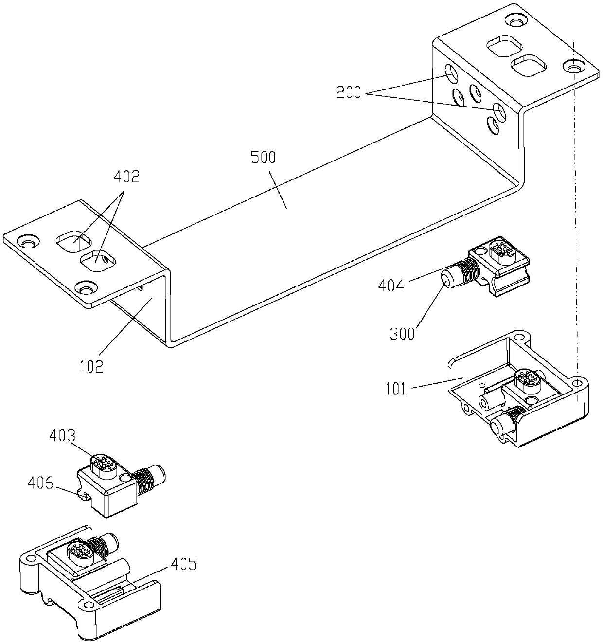
[0046] Embodiment one, such as figure 1 and 2 As shown, the manipulator 400 includes a first slider 401 placed in the lock housing 100 and connected to the inner end of the lock rod 300 as a whole, set on the surface wall of the lock housing 100 along the left and right direction (specifically: 102 on the lateral side wall) of the first sliding hole 402, the first sliding handle 403 distributed through the first sliding hole 402 and integrated with the first sliding block 401, and the locking pull sleeve sleeved on the locking bar 300 Spring 404, wherein, the outer end of locking tension spring 404 is connected with the side wall of lock housing 100 (specifically: the inner side of the longitudinal side wall of end cover 102), and the inner end is connected with the side wall surface of first slider 401, in On the inner wall of the lock case 100 (specifically, on the bottom wall of the bottom case 101 ) and along the left and right direction, a first slide rail 405 is provide...
Embodiment 2
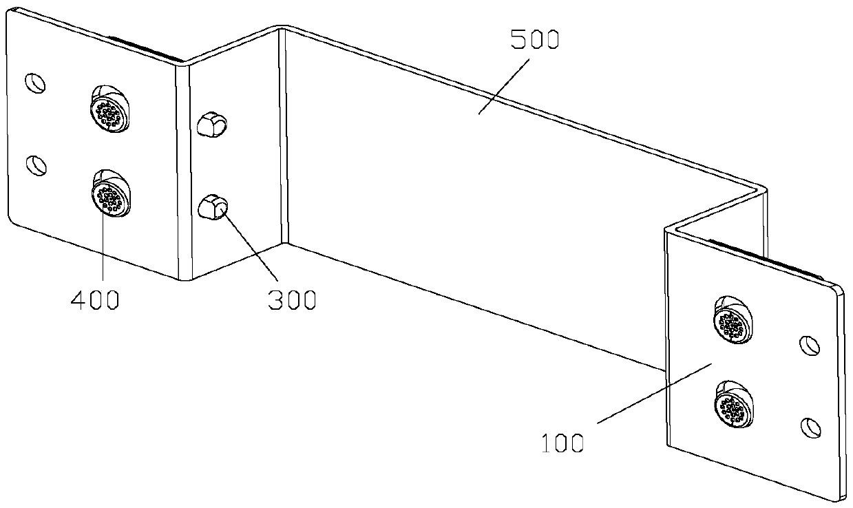
[0049] Embodiment two, such as Figure 3 to Figure 6 As shown, the handle 400 includes a second slider 407 placed in the lock housing 100, and a second sliding hole opened on the surface wall of the lock housing 100 (specifically: on the lateral side wall of the end cover 102) along the up and down direction. 408, the second sliding handle 409 distributed through the second sliding hole 408 and integrated with the second sliding block 407, the first unlocking compression spring 410 sleeved on the lock bar 300 and arranged on the lock case 100 in the up and down direction A locking spring (not shown) inside and clamped between the side wall of the second slider 407 and the side wall of the lock housing 100 (ie: the upper side wall or the lower side wall); in the lock housing 100 (specifically, on the bottom wall of the bottom case 101 ) and a second slide rail 411 is provided along the up and down direction, and a second slide groove 412 is provided on the second slide block 40...
Embodiment 3
[0053] Embodiment three, such as Figure 7 and Figure 8 As shown, the manipulator 400 includes a first electromagnetic coil 414 placed in the lock housing 100 and distributed coaxially with the lock lever 300 , and coaxially sleeved in the first electromagnetic coil 414 and the outer end of which is connected to the inside of the lock lever 300 . The ends are butted with the integrated first electromagnetic core rod 415 . Thus, similar to the structure of the electromagnetic lock, that is, through the on-off control of the first electromagnetic coil 414 and the operation of applying positive and negative currents, the principle of electric magnetization can be used to make the first electromagnetic core rod 415 move along the first electromagnetic lock. The central axis of an electromagnetic coil 414 performs a reciprocating feed movement in the first electromagnetic coil 414. When the first electromagnetic core rod 415 is stretched out from the first electromagnetic coil 41...
PUM
 Abstract
Description
Claims
Application Information
 - R&D
- Intellectual Property
- Life Sciences
- Materials
- Tech Scout
- Unparalleled Data Quality
- Higher Quality Content
- 60% Fewer Hallucinations
Browse by: Latest US Patents, China's latest patents, Technical Efficacy Thesaurus, Application Domain, Technology Topic, Popular Technical Reports.
© 2025 PatSnap. All rights reserved.Legal|Privacy policy|Modern Slavery Act Transparency Statement|Sitemap|About US| Contact US: help@patsnap.com


