Intelligent lock display device
A technology for display devices and smart locks, which is applied to display stands, display hangers, display shelves, etc., can solve problems such as unsatisfactory display effects, inconvenient purchases, time-consuming and labor-intensive problems, and achieve improved publicity and display effects, easy installation or replacement, The stable effect of the fixed rod
- Summary
- Abstract
- Description
- Claims
- Application Information
AI Technical Summary
Problems solved by technology
Method used
Image

Examples
Embodiment Construction
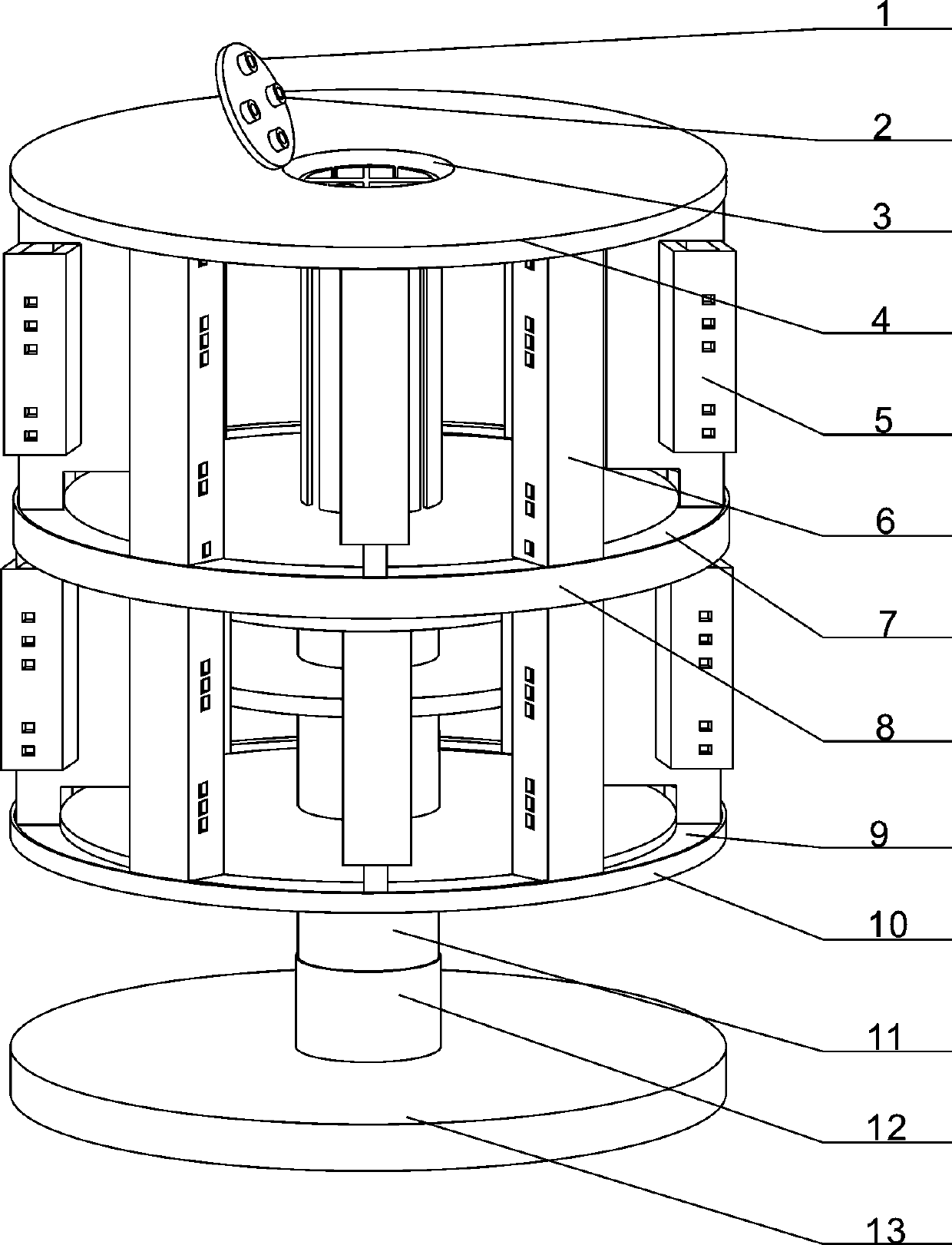
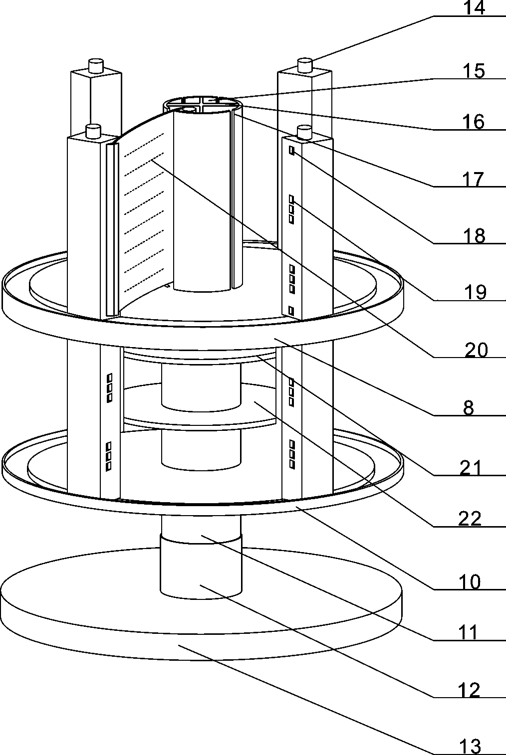
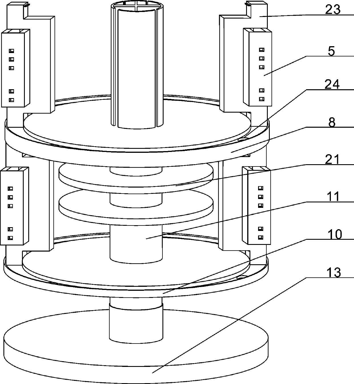
[0026] The present invention is described in further detail now in conjunction with accompanying drawing. These drawings are all simplified schematic diagrams, which only illustrate the basic structure of the present invention in a schematic manner, so they only show the configurations related to the present invention.
[0027] combined with Figure 1-7 In the given smart lock display device, a top plate 4 is provided at the upper end of the pole 11, a bottom plate 10 is provided at the bottom of the pole 11, and a Partition 8, the partition 8 divides the top plate 4 and the bottom plate 10 into two upper and lower display chambers, and the upper part of the display chamber is a hollow structure when the pole 11 is between the top plate 4 and the partition 8, Several vertical plates 16 are arranged in the upper part of the pole 11, and the inner cavity of the upper part of the pole 11 is divided into several reel placement grooves 15 by the several vertical plates 16. The op...
PUM
 Abstract
Description
Claims
Application Information
 - Generate Ideas
- Intellectual Property
- Life Sciences
- Materials
- Tech Scout
- Unparalleled Data Quality
- Higher Quality Content
- 60% Fewer Hallucinations
Browse by: Latest US Patents, China's latest patents, Technical Efficacy Thesaurus, Application Domain, Technology Topic, Popular Technical Reports.
© 2025 PatSnap. All rights reserved.Legal|Privacy policy|Modern Slavery Act Transparency Statement|Sitemap|About US| Contact US: help@patsnap.com