Pressure plate locking device

A locking device and pressing plate technology, applied in the field of locks, can solve problems such as misoperation of power wiring devices, and achieve the effect of avoiding electric shock

Pending Publication Date: 2019-05-07
ZHUHAI UNITECH POWER TECH CO LTD
View PDF9 Cites 1 Cited by
  • Summary
  • Abstract
  • Description
  • Claims
  • Application Information

AI Technical Summary

Problems solved by technology

[0007] The main purpose of the present invention is to provide a pressing plate locking device to solve the problem of potential safety hazards of misoperation in the power wiring device in the prior art

Method used


Image

  • Pressure plate locking device
  • Pressure plate locking device
  • Pressure plate locking device

Examples


Embodiment 1

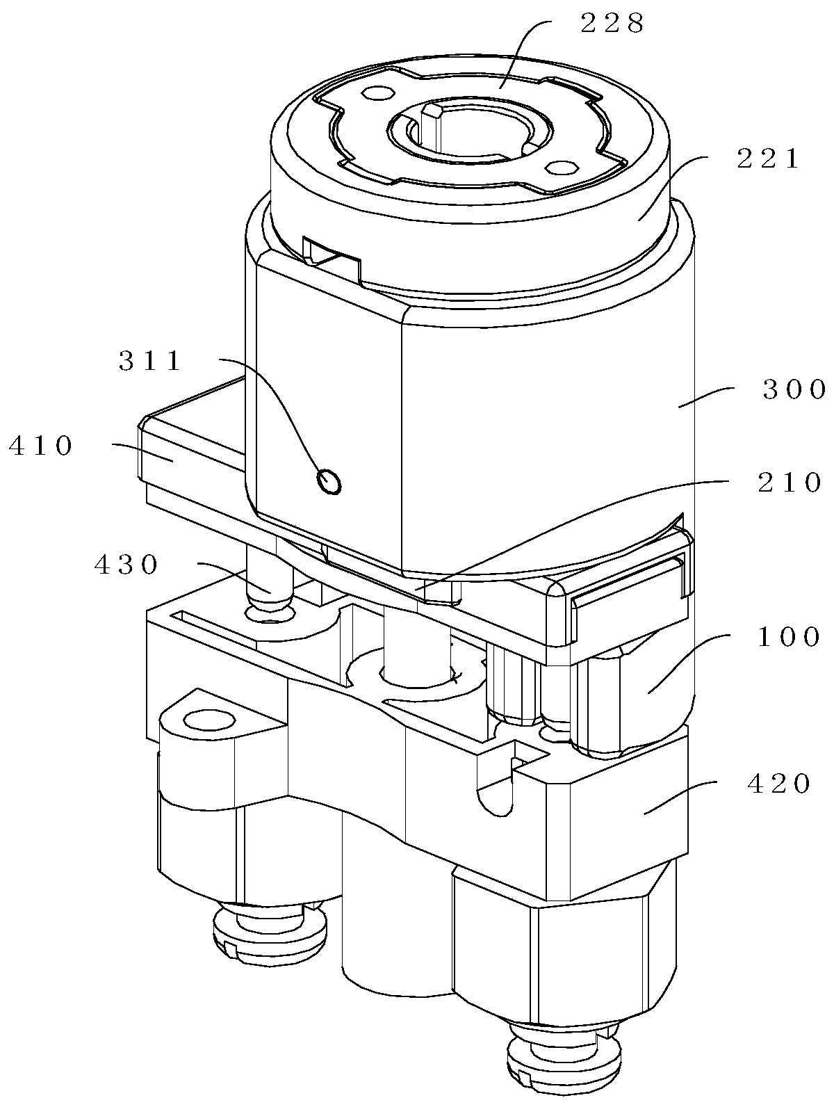
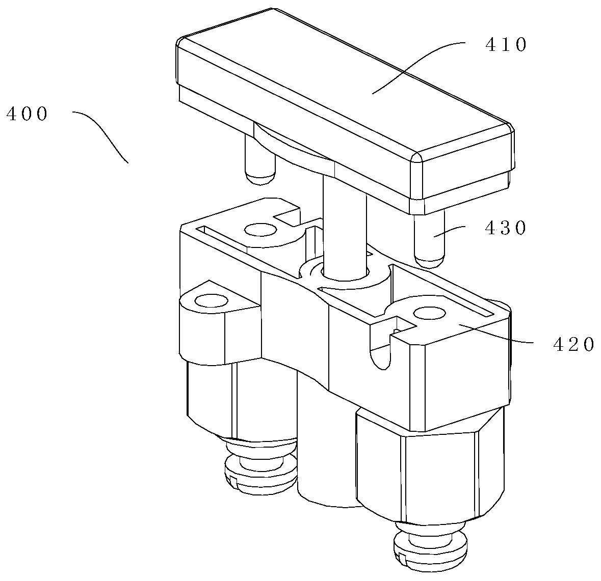
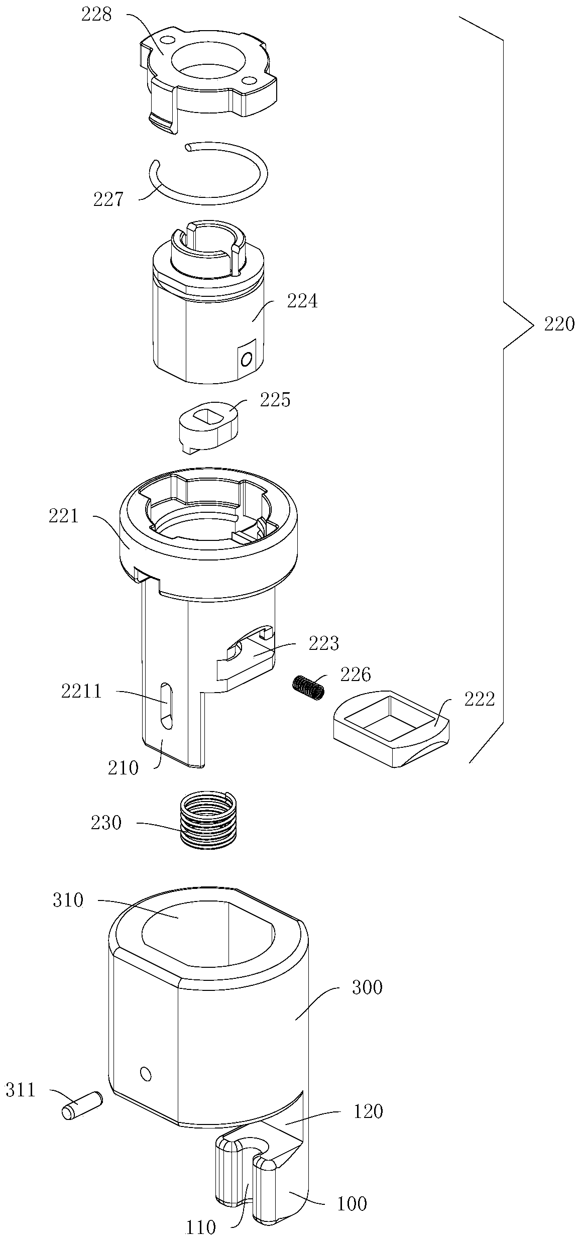
[0053] Such as figure 1 , figure 2 As shown, the pressure plate locking device includes a housing 300, a protruding structure 210, and a lock body assembly 220 for locking the protruding structure 210. A part of the housing 300 serves as the positioning and holding portion 100 and has a handle container for accommodating a pressure plate handle 410. When the pressure plate handle 410 is in the handle accommodating cavity 120, the positioning and holding portion 100 is located between the pressure plate handle 410 and the pressure plate base 420, so that the plug 430 of the pressure plate handle 410 and the conductive socket 421 of the pressure plate base 420 are held Separate state; the extended structure 210 has an extended position and a retracted position relative to the housing 300, and when the pressing plate handle 410 is in the handle accommodating cavity 120, the pressing plate handle 410 can be locked with the positioning and holding portion 100; the lock body assembly ...

Embodiment 2

[0076] The difference from the first embodiment is that the structure of the pressure plate locking device is different from that in the first embodiment, but the locking principle is similar.

[0077] Specific, such as Figure 11 to Figure 20 As shown, the extension structure 210 is a locking plate, and the first end of the locking plate extends into the housing 300 through the relief opening 312 of the housing 300, and the second end of the locking plate is always located outside and opposite to the housing 300. The position of the positioning and holding portion 100 can be changed. When the lock body assembly 220 is in the locked state, the first end of the extension structure 210 is locked with the housing 300, and the second end of the extension structure 210 is crimped on the positioning and holding portion 100 and The pressing plate handle 410 is used to prevent the pressing plate handle 410 from slipping out of the handle containing cavity 120.

[0078] When the plate need...


PUM


Abstract

The invention provides a pressure plate locking device. The pressure plate locking device comprises: a housing, wherein a part of the housing is taken as a positioning holding portion and has a handleholding cavity for accommodating a pressure plate handle, when the positioning holding portion is located between the pressure plate handle and a pressure plate base, a plug of the pressure plate handle is in a state of separation from the conductive jack of the pressure plate base; a protruding structure having a protruding position and a retracted position relative to the housing, wherein whenthe pressure plate handle is in the handle holding cavity, the pressure plate handle can be locked with the positioning holding portion; and a lock body module configured to lock the protruding structure, wherein the lock body module is arranged in the lock body holding cavity of the housing, and has a lock state and an unlock state, when the lock body module is located in the locking state, the lock body module locks the protruding structure, and when the lock body module is in the unlock state, the lock body module unlocks the protruding structure. The problem of the safety hazard of the erroneous operation of the power wiring device is solved in the prior art.

Description

Technical field [0001] The present invention relates to the technical field of locks, in particular to a pressure plate locking device. Background technique [0002] The wire spring type pressure plate is a common power wiring device, including a base and a handle. There are two sockets on the base and two conductive plugs on the corresponding handle. The bottom of the handle is connected to the base through a spring and a shaft. The spring makes The handle can snap back to the base. By pulling up and rotating the handle, the two conductive plugs can be inserted or pulled out and rotated to stagger the two sockets. When inserted, the power lines connected to the two sockets are connected, and when they are staggered, the power lines connected to the two sockets are cut off. [0003] There is no effective control method for the operation of the secondary pressure plate of the protection device in the power system. During maintenance, the operation and maintenance personnel will wi...

Claims


Application Information

Patent Timeline
Patent Type & Authority Applications(China)
IPC IPC(8): H02B1/015
Inventor 陈钦文修洪江褚兆勇陈志鸿
Owner ZHUHAI UNITECH POWER TECH CO LTD
Why Eureka
Try Eureka