
Forced locking device for secondary pressing plate and forced locking method for secondary pressing plate

A secondary pressure plate and locking device technology, applied in substation/switch layout details, electrical components, etc., can solve problems such as cumbersome installation, No. Cost saving and simple structure

Active Publication Date: 2015-11-04
STATE GRID SHANDONG ELECTRIC POWER +1
View PDF7 Cites 12 Cited by
  • Summary
  • Abstract
  • Description
  • Claims
  • Application Information

AI Technical Summary

Problems solved by technology

Accidents caused by artificially enlarged accidents caused by the secondary pressure plate of the protection device occasionally occurred. For example, in April 2008, the ratio differential protection of No. The substation tripped, resulting in no electricity in the two 110kV substations
In June 2012, a single-phase 330kV line of a 330kV substation was grounded instantaneously, and the protection tripped by mistake. The direct outlet tripped three phases due to mis-injection of the communication triple-trip pressure plate, and the 330kV line was blacked out.
In August 2014, a 330kV substation leapfrogged and tripped due to missing switch outlet pressure plate and failure of the pressure plate, resulting in no electricity in the 330kV substation
[0007] The defect of the above technology is that it is impossible to realize the mandatory locking of input and exit states in the true sense
When the operation and maintenance personnel put in the conventional protection connecting sheet type secondary pressure plate, although the pressure plate state sensor shows that the position is correct, there is a loophole that the pressure plate pressure joint is not crimped firmly, and the protection device cannot operate normally at the exit; at the same time, it is detected by the non-contact sensor Influenced by the position accuracy, when judging whether the secondary pressure plate is out of operation only through the light indication, there is a possibility that the conventional protection connecting piece type secondary pressure plate is not completely disconnected; in addition, although the logical association control of anti-misoperation locking is carried out on the secondary equipment, However, since there is no guarantee for the forced locking of the secondary protection pressure plate of the relay protection device, if there is a problem with the state sensor of the secondary pressure plate at this time, the microcomputer anti-misoperation locking system will lose its effect on the associated locking logic of the secondary pressure plate of the protection device during operation. , the indirect prompt locking function of the secondary pressure plate will be useless, which brings a huge hidden danger to the safe and stable operation of the equipment during the switching operation; finally, when installing and debugging, it is necessary to install a pressure plate state collector on each protective screen. And each pressing plate is wired, the installation is cumbersome, and it is impossible to realize the simple installation of the secondary pressing plate in the running state

Method used


Image

  • Forced locking device for secondary pressing plate and forced locking method for secondary pressing plate
  • Forced locking device for secondary pressing plate and forced locking method for secondary pressing plate
  • Forced locking device for secondary pressing plate and forced locking method for secondary pressing plate

Examples


Embodiment 1

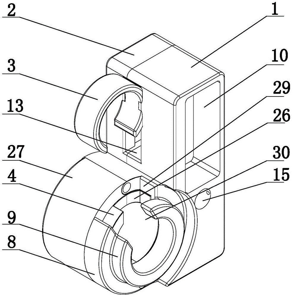
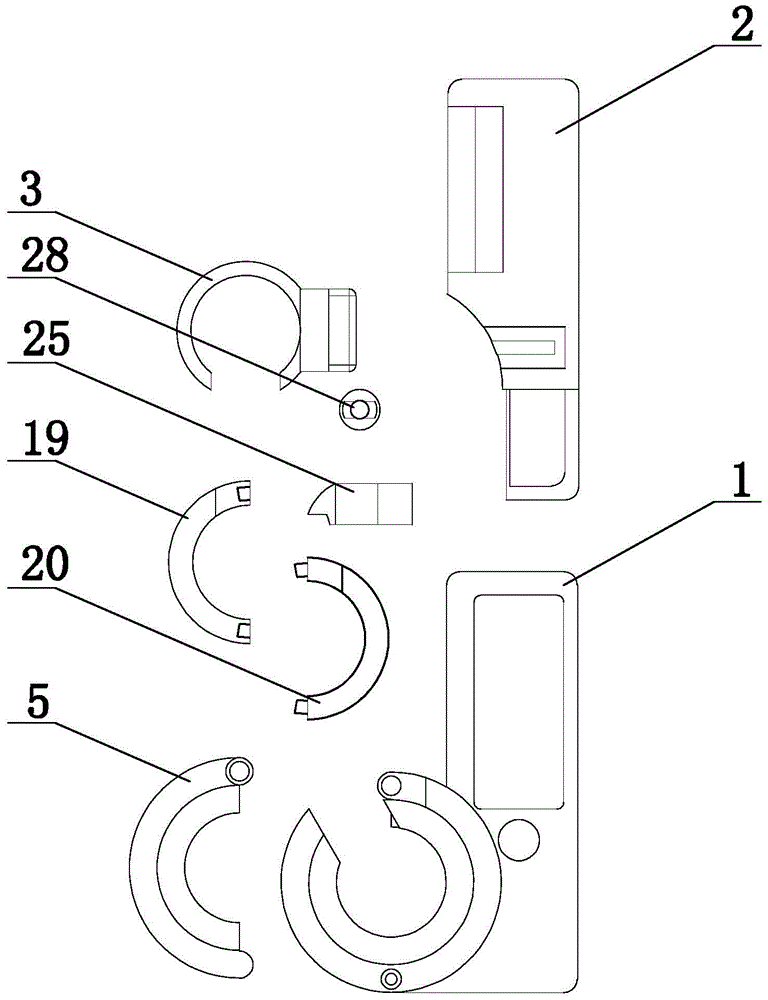
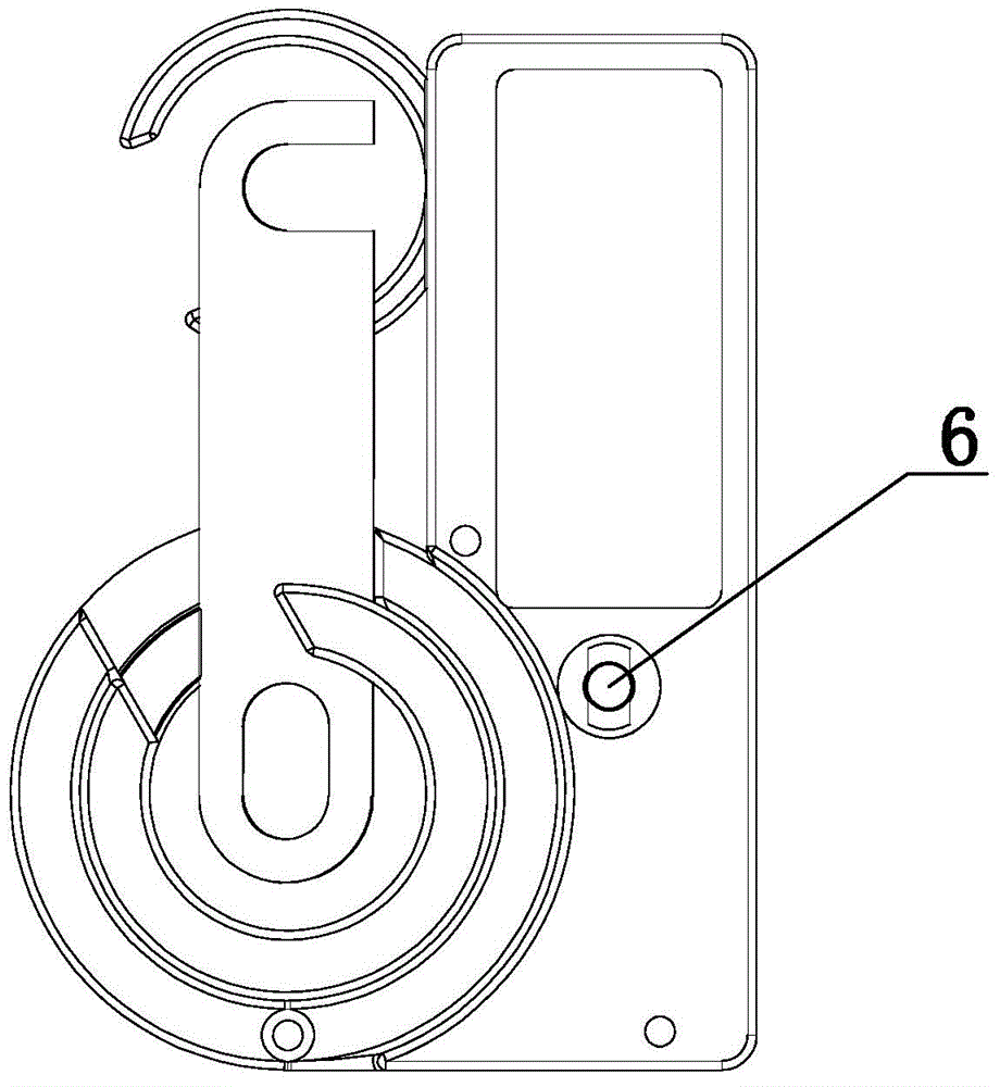
[0051] Embodiment 1: The secondary pressure plate forced locking device according to the present invention includes a casing, and also includes the following components: upper casing 1, lower casing 2, static contact ferrule 3, internal rotating shaft 4 of ferrule, and locking sleeve The left half of the base 5, the internal lock 6 and the RFID chip 7, the upper shell 1 is provided with the moving contact lock sleeve 8, the rotation track groove guard plate 9, the RFID chip installation groove 10 and the groove 11, the rotation track groove Guard plate 9 is located in moving contact lock sleeve 8, and is fixedly connected, and RFID code chip installation groove 10 side is provided with keyhole 15; Both lower shell 2 and upper shell 1 are provided with screw holes, and are connected by bolts. The upper shell 1 and the lower shell 2 are fixedly connected in the screw hole, and the lower shell 2 is provided with a groove B12 corresponding to the groove 11 of the upper shell 1, and...

Embodiment 2

[0052] Embodiment 2: On the basis of the structure described in Embodiment 1, the static contact ferrule moving groove 13 includes a slider sliding track and a connecting block sliding track, the section of the slider sliding track is adapted to the slider section, and the connecting block sliding track The cross-section is less than the cross-section of the slide block, so that the slide block 18 can only move in the slide block sliding track, but cannot pass the connecting block sliding track.

Embodiment 3

[0053] Embodiment 3: On the basis of the structure described in Embodiment 2, the locking sleeve clamping base 27 is set on the moving contact base of the pressure plate, the moving contact lock sleeve 8 is set on the moving contact of the pressure plate, and the pressure plate connecting piece Pass through the slot 26 of the connecting piece.


PUM


Abstract

The invention provides a forced locking device for a secondary pressing plate and a forced locking method for the secondary pressing plate, and belongs to the field of misoperation prevention devices of power systems. The device comprises a housing, and also comprises an upper case, a lower case, a static contact clamping sleeve, a clamping sleeve internal rotating shaft, a locking sleeve dead clamping substrate left side, an internal locking tool, and an RFID code sheet. The upper case is provided with a movable contact locking sleeve, a rotating track slot protection board, an RFID code sheet installation groove, and a groove. The device can achieve the forced locking of the pressing plate, can enable the pressing plate to be completely disconnected, can effectively record the in-service and out-of-service states of the pressing plate, and can achieve installation when the secondary pressing plate is in operation.

Description

technical field [0001] The invention provides a forced locking device for a secondary pressing plate and a forced locking method thereof, which belong to the field of anti-misoperation devices for power systems. Background technique [0002] Substation switching operation is divided into two parts: switching on and off of primary equipment and corresponding secondary equipment. In the operation of secondary equipment, switching on and off of the secondary pressure plate of the protection device is the most important part. [0003] When the primary equipment fails, the secondary pressure plate installed on the protective screen is used to switch on and off the function of the protective device and the trip outlet circuit. Corresponding function, accurate judgment, reliable action to remove the key link of fault point. [0004] Whether the secondary pressure plate is put in and out is directly related to the protection function and whether the action outlet can function norma...

Claims


Application Information

Patent Timeline
Patent Type & Authority Applications(China)
IPC IPC(8): H02B1/00
Inventor 贾栋尚许宝强宋元江季素云冯忠奎刘兴华杨成华李鑫王建东王东升王双柱孙学书翟闻铁继涛司书凯杨敬瑀耿晓辉耿立平魏剑萍宋明慧朱训华卜晨晨高盛于红郭艳张辰商涛张朋丰王欣谭丽王玉张勇王军高川胡博邻王焱王天勇高尚朱兴东白桦
Owner STATE GRID SHANDONG ELECTRIC POWER
Learn More