Axial flow impeller with cut blades

A technology for axial flow impellers and cutting blades, which is applied in the field of axial flow impellers, can solve the problems of low versatility in the use of axial flow impellers, and achieve the effects of improving processing consistency, reducing processing difficulty, and reducing development costs

Active Publication Date: 2019-05-10
SHANGHAI NAUTILUS GENERAL EQUIP MFG CO LTD
View PDF12 Cites 3 Cited by
  • Summary
  • Abstract
  • Description
  • Claims
  • Application Information

AI Technical Summary

Problems solved by technology

[0005] An axial flow impeller with cuttable blades, aiming to solve the problem of low versatility in the use of axial flow impellers in the prior art

Method used


Image

  • Axial flow impeller with cut blades
  • Axial flow impeller with cut blades
  • Axial flow impeller with cut blades

Examples


Embodiment Construction

[0036] In order to make the object, technical solution and advantages of the present invention more clear and definite, the present invention will be further described in detail below with reference to the accompanying drawings and examples. It should be understood that the specific embodiments described here are only used to explain the present invention, not to limit the present invention.

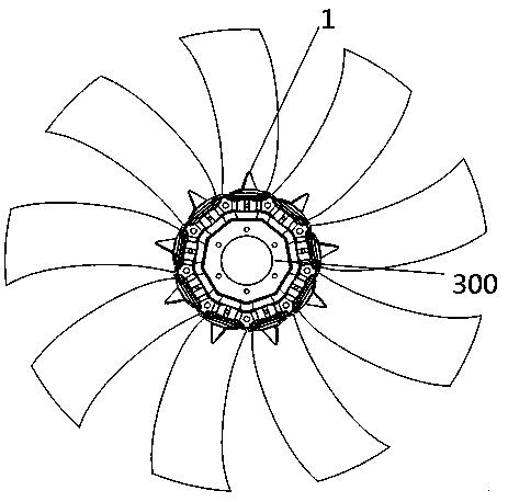
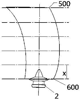
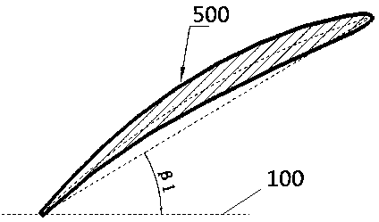
[0037] Please also see Figure 1-Figure 18 . The present invention provides an axial flow impeller with cuttable blades, which includes a hub structure 300 and several blades 1 arranged on the hub structure 300, such as figure 2 As shown, the blade 1 can be cut along its width direction, that is, after the blade 1 is cut, the cutting section on the blade 1 is a cross section in the width direction, and as the blade 1 is cut successively, The height of the blades 1 decreases gradually. Further, the airfoil installation angle of the cutting section of the blade 1 is linearly negatively...


PUM


Abstract

The invention discloses an axial flow impeller with cut blades. The axial flow impeller comprises a hub structure, and multiple blades arranged on the hub structure; the blades can be cut in the widthdirections; wing mounting angles of cut sections of the blades are in linear negative correlation in the height directions of the blades; wing chord lengths of the cut sections of the blades are in linear positive correlation in the height directions of the blades; the airflow axial component speeds of all the cut sections of the blades in the height directions of the blades are equal; the totalpressures of all the cut sections of the blades in the height directions of the blades are equal; after the blades are cut as needed, the pneumatic characteristics of the axial flow impeller can be maintained invariable, so that the pneumatic efficiency cannot be attenuated, and the air volume can be changed; and after the blades with one height are produced only by one set of molds, the blades are cut according to actual application demands to obtain the blades with different heights, so that a performance curve capable of being reached by the axial flow impeller is increased, and the use generality is improved.

Description

technical field [0001] The invention relates to the technical field of ventilation equipment, in particular to an axial flow impeller with cuttable blades. Background technique [0002] Axial flow impeller is the most common type of ventilation machinery in the fan industry at present. The blade is the key component of the axial flow impeller to provide air flow. In the prior art, the motor is directly connected to the hub, which is limited by the fixed number of motor stages, and the speed that can be achieved is relatively small. , resulting in fewer performance curves for axial flow impellers. For ventilation systems with different performance requirements, it is necessary to determine the aerodynamic performance parameters before performing blade design and three-dimensional processing of the blades, that is, for different aerodynamic performance parameter requirements, In the prior art, it is necessary to remanufacture a plurality of axial flow impellers with different ...

Claims


Application Information

Patent Timeline
Patent Type & Authority Applications(China)
IPC IPC(8): F04D29/32F04D29/34F04D29/38
Inventor 刘勇唐照付金守清王倩张劲戈
Owner SHANGHAI NAUTILUS GENERAL EQUIP MFG CO LTD
Why Eureka
Try Eureka