A smart TV antenna and a smart TV

A technology for smart TVs and TVs, applied in the field of communications, can solve problems such as blind spots for TV wireless signal reception, hinder TV reception of wireless signals, etc., and achieve data transmission throughput rate and omnidirectional improvement, and vertical polarization characteristics. , the effect of horizontal radiation suppression

Active Publication Date: 2021-08-06
SHENZHEN TCL NEW-TECH CO LTD
View PDF7 Cites 0 Cited by
  • Summary
  • Abstract
  • Description
  • Claims
  • Application Information

AI Technical Summary

Problems solved by technology

[0003] The main purpose of the present invention is to provide a smart TV antenna, which aims to solve the problem that the screen and metal panel of the TV block the TV from receiving wireless signals, causing the TV to have a wireless signal receiving blind area

Method used


Image

  • A smart TV antenna and a smart TV
  • A smart TV antenna and a smart TV
  • A smart TV antenna and a smart TV

Examples


Embodiment Construction

[0022] The following will clearly and completely describe the technical solutions in the embodiments of the present invention with reference to the accompanying drawings in the embodiments of the present invention. Obviously, the described embodiments are only part of the embodiments of the present invention, not all of them. Based on the embodiments of the present invention, all other embodiments obtained by persons of ordinary skill in the art without creative efforts fall within the protection scope of the present invention.

[0023] It should be noted that all directional indications (such as up, down, left, right, front, back...) in the embodiments of the present invention are only used to explain the relationship between the components in a certain posture (as shown in the accompanying drawings). Relative positional relationship, movement conditions, etc., if the specific posture changes, the directional indication will also change accordingly.

[0024] In addition, the ...


PUM


Abstract

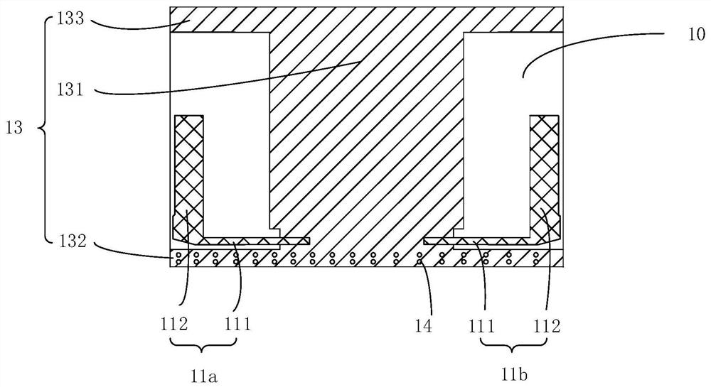
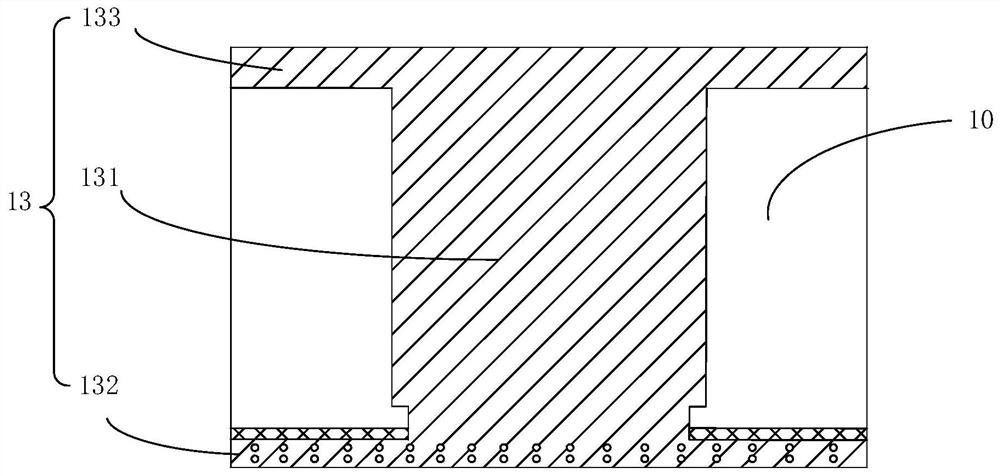
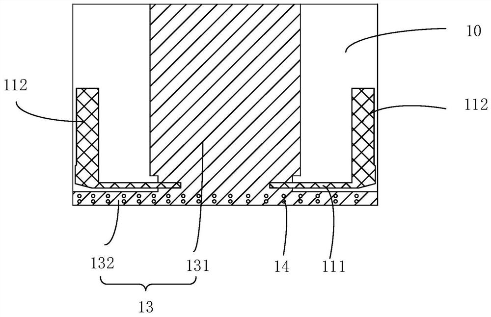
The present invention provides a smart TV antenna and a smart TV. The smart TV antenna is arranged in the TV. The smart TV antenna includes: a printed circuit board, and the printed circuit board includes opposite first surface and a second surface; a grounded metal layer, the grounded metal layer is disposed on the first surface; at least two radiation regions, the at least two radiation regions are disposed on the second surface; a metal loading layer, the metal The loading layer is disposed on the second surface and is located between the radiation areas, and the metal loading layer is electrically connected to the ground metal layer through a through hole penetrating the printed circuit board, and the radiation area is connected to the radiation area. The metal loading layer is electrically connected to strengthen the vertical polarization characteristic of the radiation region. The invention strengthens the vertical polarization characteristic, is beneficial to improve the data transmission throughput rate and omnidirectionality, and reduces the blind area of ​​the wireless signal of the TV set.

Description

technical field [0001] The invention relates to the field of communication technology, in particular to an antenna for a smart TV and a smart TV. Background technique [0002] With the improvement of living standards, the size of television sets has become larger and larger. In the prior art, the data traffic of the TV set is provided by the home wireless network, and the screen of the large-size TV set and the metal panel behind the screen will hinder the TV set from receiving the wireless network, causing the TV set to fail to receive the wireless network. Blind spots affect the working performance of the TV. Contents of the invention [0003] The main purpose of the present invention is to provide a smart TV antenna, aiming to solve the problem that the screen and metal panel of the TV block the TV from receiving wireless signals, resulting in blind spots for receiving wireless signals in the TV. [0004] In order to achieve the above object, the present invention pro...

Claims


Application Information

Patent Timeline
Patent Type & Authority Patents(China)
IPC IPC(8): H01Q1/22H01Q1/36H01Q1/38H01Q1/48H01Q1/50
Inventor 尹柳中郭康清王子同谢仁礼杨福军
Owner SHENZHEN TCL NEW-TECH CO LTD
Why Eureka
Try Eureka