Bearing outer ring clamping device
A technology of bearing outer ring and clamping device, which is applied in the direction of transportation and packaging, conveyor objects, etc., and can solve the problems that cannot meet the production needs of large quantities
- Summary
- Abstract
- Description
- Claims
- Application Information
AI Technical Summary
Problems solved by technology
Method used
Image
Examples
Embodiment 1
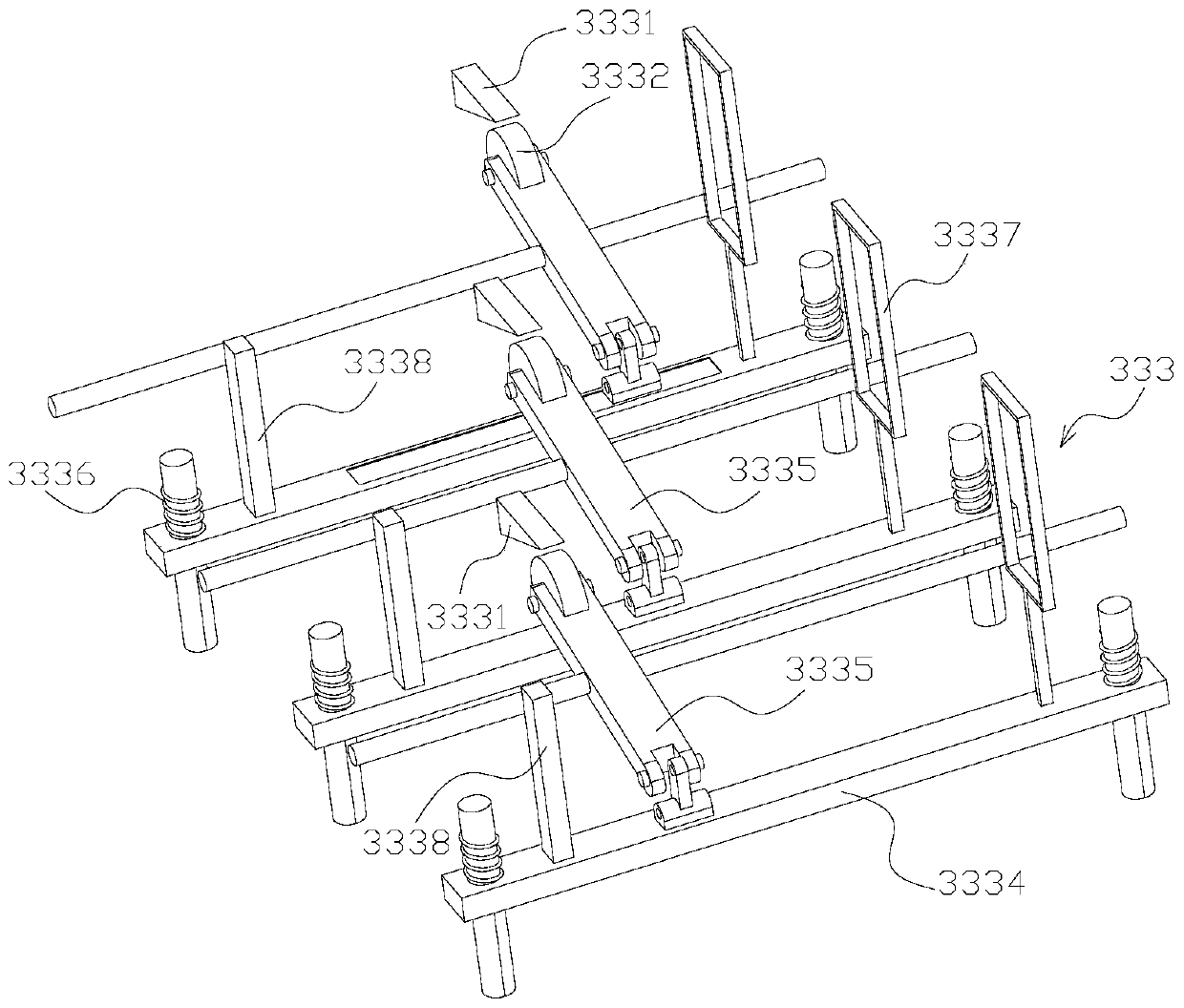
[0050] Such as Figure 1-7As shown, for the material distribution conveyor belt 330 used for bearing production, one end of the material distribution conveyor belt 330 is the feed end, and the other end is the discharge end, and the material distribution conveyor belt 330 is provided with interval maintenance components 331 along its conveying direction. The maintenance assembly 331 includes two splints arranged in a vertical shape, the width direction of the splints is consistent with the width direction of the material distribution conveyor belt 330, the two outer sides of the splints are respectively provided with baffles 332, the baffles 332 are fixed on the frame, and the baffles 332 The layout range of the ring is consistent with the range of the track that the ring is conveyed on the distribution conveyor belt 330. The ring is vertically constrained in the area enclosed by the splint and the baffle 332, and the baffle 332 at the discharge end is provided for maintaining ...
Embodiment 2
[0054] Such as image 3 , 4 , 5, 6, and 8, a conveying device for multi-size bearing production, including a material distribution conveyor belt 330, on which material distribution conveyor belt 330 is provided with maintenance components 331 at intervals along its conveying direction, and the maintenance components 331 include two vertical arrangements The splint, the width direction of the splint is consistent with the width direction of the material distribution conveyor belt 330, the splint includes a fixed plate body 3311 and a movable plate body 3312, the movable plate body 3312 is arranged on the plate surface of the two splints facing each other, the movable plate body 3312 Cooperate with the detachable connection of the fixed plate body 3311, and replace different movable plates to adjust the distance between the splints. This enables reliable conveying of various types of rings.
[0055] An outer side of the splint is provided with baffles 332 respectively, and the...
Embodiment 3
[0059] Such as Figure 9 As shown, the feeding unit for the bearing polishing process includes a frame, a feeding mechanism 310 for operators to add ring parts is arranged on the frame, and a feeding mechanism 350 is respectively arranged on the front side of each polishing device 360360. A material distributing mechanism is arranged between the mechanism 310 and the feeding mechanism 350 , and the material distributing mechanism distributes and transports the ring pieces on the feeding mechanism 310 to each feeding mechanism 350 .
[0060] Specifically, the material distribution mechanism includes a material distribution conveyor belt 330 arranged horizontally, the feed end of the material distribution conveyor belt 330 is arranged correspondingly to the discharge port of the feeding mechanism 310, and the discharge end of the material distribution conveyor belt 330 is provided with each discharge Each discharge port is arranged corresponding to the feed port of each feed mec...
PUM
 Abstract
Description
Claims
Application Information
 - R&D
- Intellectual Property
- Life Sciences
- Materials
- Tech Scout
- Unparalleled Data Quality
- Higher Quality Content
- 60% Fewer Hallucinations
Browse by: Latest US Patents, China's latest patents, Technical Efficacy Thesaurus, Application Domain, Technology Topic, Popular Technical Reports.
© 2025 PatSnap. All rights reserved.Legal|Privacy policy|Modern Slavery Act Transparency Statement|Sitemap|About US| Contact US: help@patsnap.com


