HUD

A head-up display device and technology for displaying light, applied in projection devices, televisions, transportation and packaging, etc., can solve problems such as brightness reduction, and achieve the effects of suppressing projection, good visual confirmation, and improving contrast.

Active Publication Date: 2021-03-19
DENSO CORP
View PDF7 Cites 0 Cited by
  • Summary
  • Abstract
  • Description
  • Claims
  • Application Information

AI Technical Summary

Problems solved by technology

As a result, the brightness of the virtual image decreases, so although the disturbance light becomes less likely to be reflected, it cannot be said to be good from the viewpoint of the contrast of the virtual image.

Method used


Image

  • HUD
  • HUD
  • HUD

Examples


no. 1 approach

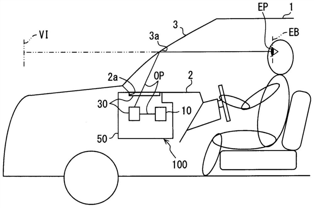
[0024] Such as figure 1 As shown, the HUD device 100 of the first embodiment is mounted on a vehicle 1 which is a type of mobile body, and is housed in an instrument panel 2 . The HUD device 100 projects an image on the windshield 3 as projection means of the vehicle 1 . As a result, the HUD device 100 virtual-displays the image so that the occupant can visually recognize it. That is, the display light of the image reflected by the front windshield 3 reaches the visual confirmation area EB set in the interior of the vehicle 1, so that the occupant with the eye point EP in the visual confirmation area EB perceives the display light as Virtual image VI. Also, the occupant can recognize various information displayed as the virtual image VI. Examples of various information displayed as the virtual image VI include vehicle state values ​​such as vehicle speed and remaining fuel level, and vehicle information such as road information and visual field assistance information.

[0...

no. 2 approach

[0065] Such as Figure 5 As shown, the second embodiment is a modified example of the first embodiment. Regarding the second embodiment, the description will focus on points different from the first embodiment.

[0066] The light guide unit 230 in the HUD device 200 of the second embodiment has a first phase element 32 , a second phase element 237 , a multilayer mirror 241 , a magnifying glass 44 , and a linear polarizer 47 . Among them, the first phase element 32 , the magnifying glass 44 , and the linear polarizer 47 are the same as those in the first embodiment.

[0067] The second phase element 237 is arranged on the optical path OP at a position closer to the front windshield 3 than the first phase element 32 , particularly between the first phase element 32 and the multilayer mirror 241 . Specifically, the second phase element 237 is a 1 / 4 wavelength plate formed in a flat plate shape. The optical axis 37 a of the second phase element 237 is set corresponding to the a...


PUM


Abstract

The light guide part (30) of the head-up display device of the present invention is provided with: a first phase element (32), which is arranged on the optical path (OP), and converts the linearly polarized display light from the projection part (10) into circularly polarized light, and has a reflective surface (33) facing the projection component side and arranged to be able to reflect light from the projection component side to the projection component side; the second phase element (37), which is configured on the optical path at a higher position than the first phase element (32) At a position close to the projection component side, a phase difference of 1 / 4 wavelength is given to the display light converted into circularly polarized light by the first phase element (32), thereby being converted into linearly polarized light; and a linear polarizer (47), which is disposed on the optical path at a position closer to the projection component side than the second phase element (37), guides the light whose polarization direction is along the light guide axis, and guides the polarization direction along the direction perpendicular to the light guide axis The light of the light-shielding axis is blocked, and the display light is guided to the projection part side by aligning the light-guiding axis with the polarization direction of the display light converted into linearly polarized light by the second phase element (37).

Description

[0001] This application is based on Japanese Patent Application No. 2016-184951 filed on September 22, 2016, and the contents described therein are incorporated herein. technical field [0002] The present disclosure relates to a head-up display device (hereinafter, simply referred to as a HUD device) that is mounted on a mobile body and displays a virtual image so that a rider can visually recognize it. Background technique [0003] Conventionally, there is known a HUD device that is mounted on a mobile body and that displays a virtual image so that a passenger can visually recognize it. The HUD device disclosed in Patent Document 1 includes a projection unit and a light guide unit. The projection unit projects image display light as linearly polarized light. The light guide forms an optical path that guides the display light to the projection member. [0004] Here, the light guide has an optical lens and a circular polarizing plate. The optical lens is disposed on the o...

Claims


Application Information

Patent Timeline
Patent Type & Authority Patents(China)
IPC IPC(8): G02B27/01B60K35/00
CPCH04N5/74B60K35/00G02B27/01G02B27/0101B60K2370/1529G02B27/286G02B5/30B60K2370/334G02B2027/0118B60K2370/25G02B5/3083G02B5/08G02B5/3025B60K2370/167G02B5/0816G03B21/006G03B21/28
Inventor 南原孝启
Owner DENSO CORP
Why Eureka
Try Eureka