Inverse solution method, device and robot of mechanical arm

A technology of manipulator and arm length, which is applied in the field of manipulators, can solve problems such as the complexity of the inverse solution process of six-axis manipulators, and achieve the effect of increasing speed and ensuring timeliness

Active Publication Date: 2021-02-02
海安苏博机器人科技有限公司
View PDF3 Cites 0 Cited by
  • Summary
  • Abstract
  • Description
  • Claims
  • Application Information

AI Technical Summary

Problems solved by technology

[0005] Embodiments of the present invention provide a method, device, and robot for inverse solution of a mechanical arm, to at least solve the technical problem in the prior art that the inverse solution process of a six-axis mechanical arm that does not meet the PIEPER criterion is relatively complicated

Method used


Image

  • Inverse solution method, device and robot of mechanical arm
  • Inverse solution method, device and robot of mechanical arm
  • Inverse solution method, device and robot of mechanical arm

Examples


Embodiment 1

[0029] According to an embodiment of the present invention, an embodiment of an inverse solution method of a robotic arm is provided. It should be noted that the steps shown in the flow chart of the accompanying drawings can be executed in a computer system such as a set of computer-executable instructions, Also, although a logical order is shown in the flowcharts, in some cases the steps shown or described may be performed in an order different from that shown or described herein.

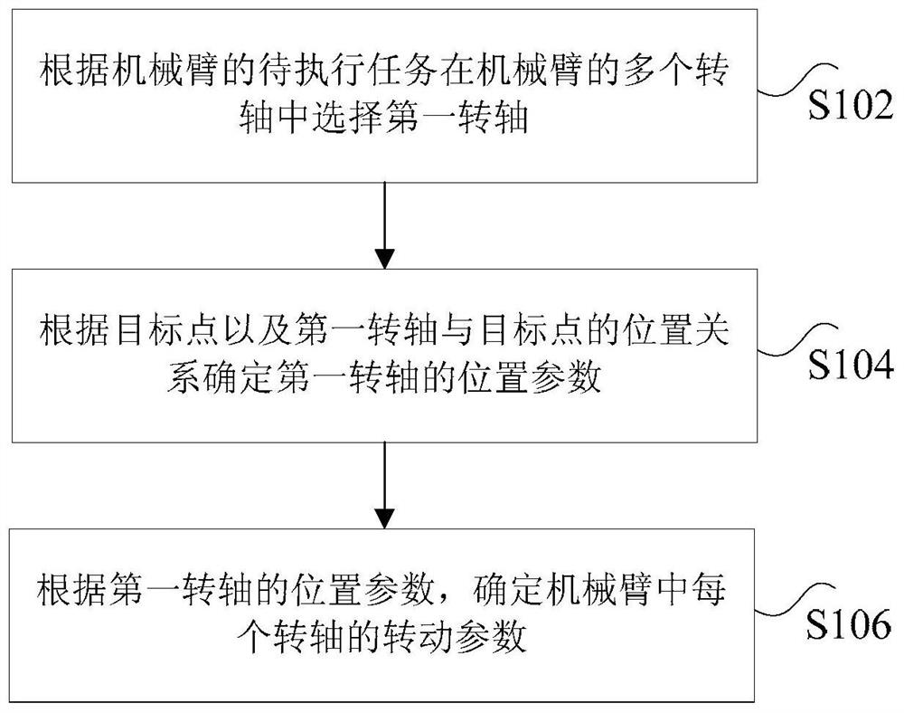
[0030] figure 1 is a flow chart of an inverse solution method for a mechanical arm according to an embodiment of the present invention, such as figure 1 As shown, the method includes the following steps:

[0031] Step S102, according to the task to be performed of the robot arm, select the first rotation axis among the multiple rotation axes of the robot arm, wherein the first rotation axis and the target point have a positional relationship corresponding to the task to be performed, and the targ...

Embodiment 2

[0075] According to an embodiment of the present invention, an embodiment of an inversion device for a mechanical arm is provided, Figure 4 is a schematic diagram of an inversion device for a mechanical arm according to an embodiment of the present invention, such as Figure 4 As shown, the device includes:

[0076] The selection module 40 is used to select the first rotation axis among the plurality of rotation axes of the robot arm according to the task to be performed by the robot arm, wherein the first rotation axis and the target point have a positional relationship corresponding to the task to be performed, and the target point is used to represent the The position that the actuator connected to the end robot arm needs to reach when performing the task to be performed.

[0077] The first determining module 42 is configured to determine the position parameter of the first rotating shaft according to the target point and the positional relationship between the first rota...

Embodiment 3

[0100]According to an embodiment of the present invention, a robot is provided, including the inverse solution device of the mechanical arm described in Embodiment 2.


PUM


Abstract

The present invention discloses a method for finding an inverse kinematics solution of a robotic arm, a device, and a robot. The method comprises: selecting, according to a pending task of a robotic arm, a first axis of rotation from a plurality of axes of rotation of the robotic arm, wherein the first axis of rotation and a target point have a positional relationship corresponding to the pending task, and the target point is used to represent a position at which an end effector of the robotic arm is required to have arrived at when the task is executed; determining a position parameter of the first axis of rotation according to the target point and the positional relationship between the first axis of rotation and the target point; and determining, according to the position parameter of the first axis of rotation, a rotation parameter of each axis of rotation of the robotic arm. The present invention resolves the technical issue in the prior art in which the process of finding an inverse kinematics solution of a six degrees of freedom robotic arm that does not satisfy the Pieper principle is highly complex.

Description

technical field [0001] The present invention relates to the field of manipulators, in particular to a method, device and robot for inverse solution of a manipulator. Background technique [0002] At present, the general six-axis manipulators on the market all meet the PIEPER criterion (that is, there are adjacent three axes parallel or the axes intersect at one point), but the main defects of the six-axis manipulators that meet the PIEPER criterion include: the space that the manipulator can reach is insufficient, And the structure tends to be single, and it is difficult to complete more actions. [0003] However, for the six-axis manipulator that does not meet the PIEPER criterion, numerical methods can only be used to solve it. The solution process is complex and needs to be approached continuously, resulting in the consumption of more computing resources, which affects the real-time performance of the six-axis manipulator. For this reason, a sequential transposition meth...

Claims


Application Information

Patent Timeline
Patent Type & Authority Patents(China)
IPC IPC(8): B25J9/16
CPCB25J9/16
Inventor 不公告发明人
Owner 海安苏博机器人科技有限公司
Why Eureka
Try Eureka