Circularly-polarized cross dipole GPS navigation antenna

A technology of GPS navigation and crossed dipoles, applied in the field of antennas, can solve the problems of unsatisfactory impedance bandwidth and beam width, increase system cost and size, etc., and achieve the effects of widening beam width, improving axial ratio, and increasing bandwidth

Pending Publication Date: 2019-05-28
SOUTH CHINA UNIV OF TECH
View PDF0 Cites 9 Cited by
  • Summary
  • Abstract
  • Description
  • Claims
  • Application Information

AI Technical Summary

Problems solved by technology

However, the circular polarization bandwidth of most traditional microstrip antennas generally does not exceed 5%. Improving the circular polarization of the microstrip patch antenna through the feed network increases the cost and size of the system, and the impedance bandwidth and beam width are not the same. not ideal

Method used


Image

  • Circularly-polarized cross dipole GPS navigation antenna
  • Circularly-polarized cross dipole GPS navigation antenna
  • Circularly-polarized cross dipole GPS navigation antenna

Examples


Embodiment

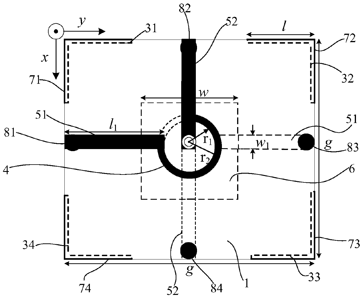
[0034] figure 1 and figure 2 They are a side view and a top view of a cross-dipole circularly polarized GPS navigation antenna according to an embodiment of the present invention, which is applied to a GPS satellite navigation terminal device. refer to figure 2 and image 3 As shown, in this embodiment, the circularly polarized crossed dipole GPS antenna includes an upper dielectric substrate 1 , a lower dielectric substrate 2 , an intermediate dielectric substrate, a radiation unit, a metal patch, a parasitic unit 6 and a feed unit 4 . The intermediate dielectric substrate is arranged between the upper dielectric substrate and the lower dielectric substrate, and is respectively perpendicular to the upper dielectric substrate and the lower dielectric substrate, and the lower surface of the lower dielectric substrate is provided with a reflection plate;

[0035] The upper dielectric substrate and the lower dielectric substrate are separated by a certain distance and arrang...


PUM


Abstract

The invention discloses a circularly-polarized cross dipole GPS navigation antenna. The antenna comprises an upper dielectric substrate, a lower dielectric substrate, an intermediate dielectric substrate, a radiation unit, a parasitic unit and a feed unit, wherein the upper dielectric substrate and the lower dielectric substrate are arranged in parallel; the intermediate dielectric substrate is arranged between the upper dielectric substrate and the lower dielectric substrate and is perpendicular to the upper dielectric substrate and the lower dielectric substrate; and a reflecting plate is arranged on the lower surface of the lower dielectric substrate. The antenna is small in size, is large in bandwidth, is wide in beam, and can be well applied to GPS satellite navigation terminal devices.

Description

technical field [0001] The invention relates to the technical field of antennas, in particular to a circularly polarized crossed dipole GPS navigation antenna. Background technique [0002] Compared with linearly polarized antennas, circularly polarized (CP) antennas not only have no strict requirements on the receiving and transmitting directions of the antenna, but also can reduce polarization mismatch, suppress multipath interference and counteract the Faraday rotation effect of the ionosphere , thus providing a stable link between the receiving antenna and the transmitting antenna. Based on the above advantages, circularly polarized antennas have been widely used in various wireless communication systems, such as wireless video identification (RFID), wireless local area network (WLAN), satellite communication (SC) and global positioning system (GPS). With the rapid development of wireless communication technology, higher requirements are put forward for wide impedance b...

Claims


Application Information

Patent Timeline
Patent Type & Authority Applications(China)
IPC IPC(8): H01Q1/36H01Q1/38H01Q1/50H01Q9/16H01Q15/24H01Q19/10
Inventor 刘雄英翟志远任琪欣范艺
Owner SOUTH CHINA UNIV OF TECH
Why Eureka
Try Eureka