An antenna arrangement and a base station

a technology of antenna arrangement and base station, which is applied in the direction of individual energised antenna arrays, resonant antennas, wireless communication, etc., can solve the problems of increasing the loss of a conventional feeding network based on narrow flexible cables, reducing the performance of low band and high band at the same time, and reducing the cost of operation. , the effect of improving the dipole bandwidth

Inactive Publication Date: 2015-12-24
CELLMAX TECH AB
View PDF2 Cites 4 Cited by
  • Summary
  • Abstract
  • Description
  • Claims
  • Application Information

AI Technical Summary

Benefits of technology

[0015]A possible range of radiators which can be used in a multiband antenna arrangement are dipoles. Today, in cellular systems, dual polarized elements are almost exclusively used, commonly in a plus/minus 45 degrees configuration. Basic T-shaped dipoles have the advantage of providing excellent radiation efficiency, but have rather poor bandwidth. The dipole bandwidth can be improved by providing more advanced structure. One such structure for a dual polarized dipole is the four-leaf clover structure as shown in FIG. 5 which also has excellent band-width performance. This dipole will give excellent result in a multiband antenna arrangement when used for the High Band antenna, but if used for the Low Band antenna, its size will be very large. Also, the distance between the dipole and the reflector is typically in the order of a quarter wavelength, thus, large Low Band dipoles will partly mask the High Band dipoles giving a

Problems solved by technology

One problem with increasing the aperture of the High Band antenna has been that the loss of a conventional feeding network based on narrow flexible cables increases more with number of radiators at higher frequencies compared with lower frequencies, and therefore part or the entire extra gain achieved by increasing the antenna aperture is lost in the feeding net

Method used


Image

  • An antenna arrangement and a base station
  • An antenna arrangement and a base station
  • An antenna arrangement and a base station

Examples


Embodiment Construction

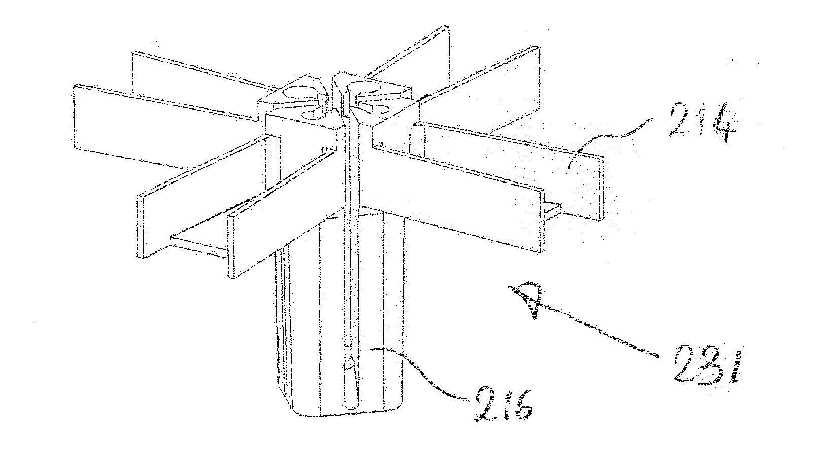
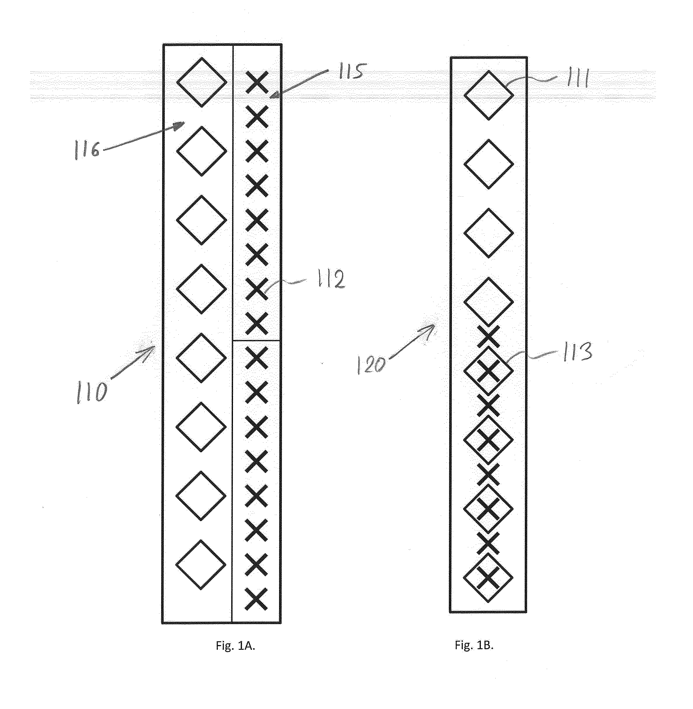
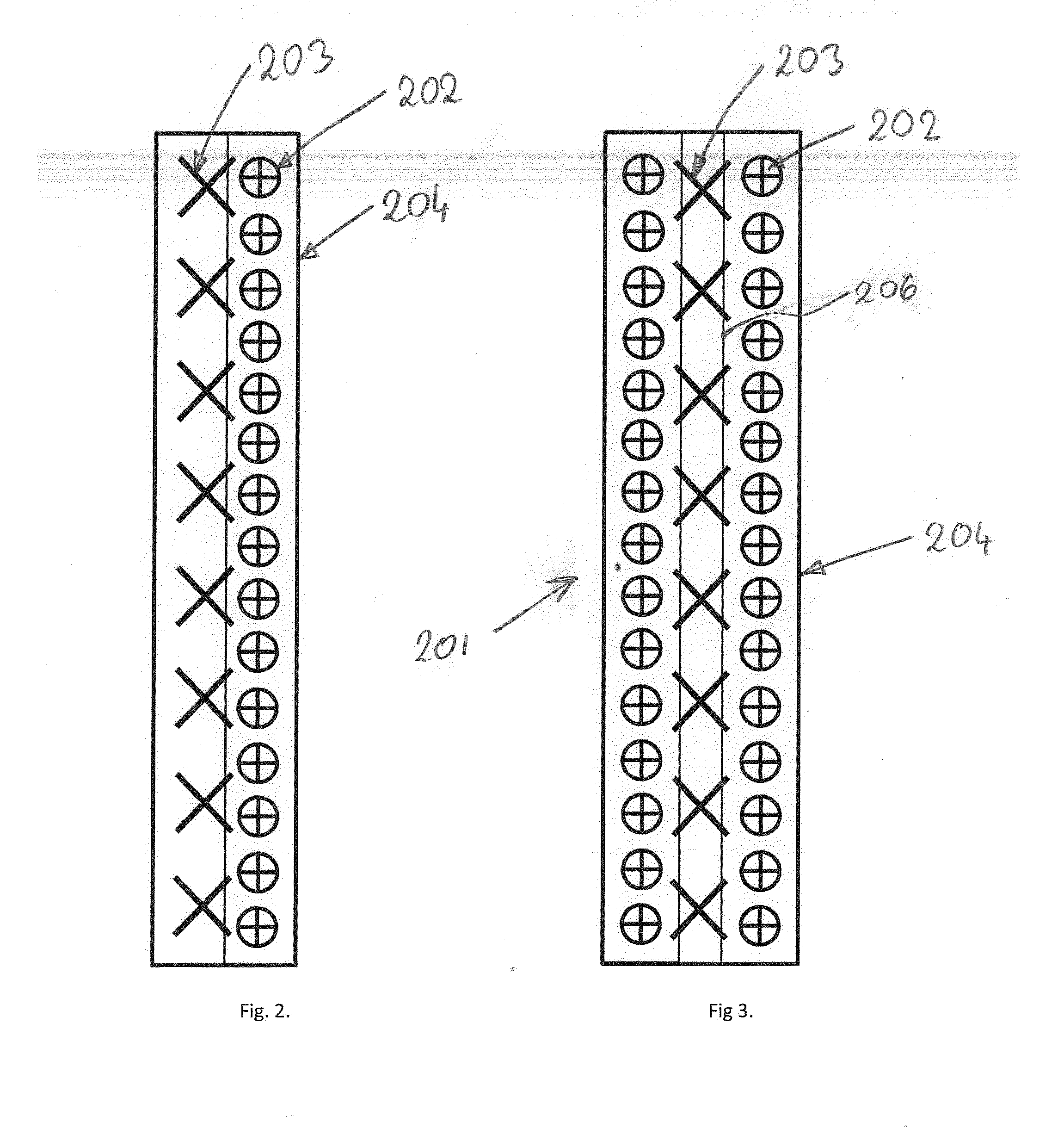
[0042]FIGS. 2-4 schematically show aspects of embodiments of the antenna arrangements according to present invention, comprising a reflector 204, and radiators 202 and 203. In FIG. 2, a first column of Low Band radiators 203 are placed on a reflector 204. A second column of High Band radiators 202 are placed next to the first column. The High Band radiators 202 are smaller than the Low Band radiators 203, and the separation between radiators is smaller than for the Low Band radiators, hence more High Band radiators are needed in order to occupy the full height of the reflector. In FIG. 3, a first column of Low Band radiators 203 is placed in the middle of the reflector 204. A second column of High Band radiators 202 is placed to one side of the first column, and a third column of High Band radiators 202 is placed on the other side of the other side of the first column. All three columns occupy the full height of the reflector 204. FIG. 4 shows a schematic side view of an embodiment ...


PUM


Abstract

An antenna arrangement for mobile communication, the antenna arrangement comprising a plurality of radiators (202, 203) for at least two different frequency bands, the plurality of radiators being placed on a reflector (204), wherein the plurality of radiators comprises a first group of radiators arranged to operate in a first frequency band of the at least two different frequency bands, wherein the plurality of radiators comprises a second group of radiators arranged to operate in a second frequency band of the at least two different frequency bands, the first group of radiators forming a first antenna, the second group of radiators forming a second antenna, wherein the radiators of the first group have the same antenna aperture, e.g. the same antenna aperture length, as the radiators of the second group.

Description

TECHNICAL FIELD[0001]The present invention relates to an antenna arrangement for mobile communication, the antenna arrangement comprising a plurality of radiators for at least two different frequency bands, the plurality of radiators being placed on a reflector. Further, the present invention relates to a base station for mobile communication comprising at least one antenna arrangement of the above-mentioned sort.BACKGROUND OF THE INVENTION[0002]A typical communications antenna arrangement may comprise a plurality of radiating antenna elements, an antenna feeding network and a reflector. The radiators are typically arranged in columns, each column of radiators forming one antenna. The radiators may by single or dual polarized; in the latter case, two feeding networks are needed per antenna, one for each polarization. Radiators are commonly placed as an array on the reflector, in most cases as a one-dimensional array extending in the vertical plane, but also two-dimensional arrays ar...

Claims


Application Information

Patent Timeline
IPC IPC(8): H01Q5/28H04B1/50H01Q1/24H04W72/04H01Q9/16H01Q19/10
CPCH01Q1/246H01Q5/28H01Q9/16H01Q19/10H04B1/50H04W72/0453H04W88/08H01Q5/42H01Q5/48H01Q19/108H01Q21/06H01P5/183
Inventor LENART, GREGOR
Owner CELLMAX TECH AB
Why Eureka
Try Eureka