Fastening element

A fastening element and fastening technology, applied in the direction of threaded fasteners, connecting components, screws, etc., can solve the problem of small loadability and achieve the effect of simplifying screw-in

Inactive Publication Date: 2019-06-07
BOSSARD AG
View PDF15 Cites 1 Cited by
  • Summary
  • Abstract
  • Description
  • Claims
  • Application Information

AI Technical Summary

Problems solved by technology

[0003] If the fastening means known from the prior art, in particular screws, are used for porous materials, this often results in the screw being pulled out of the material due to the material's low loadability and thus reduced force absorption.

Method used


Image

  • Fastening element
  • Fastening element
  • Fastening element

Examples


Embodiment Construction

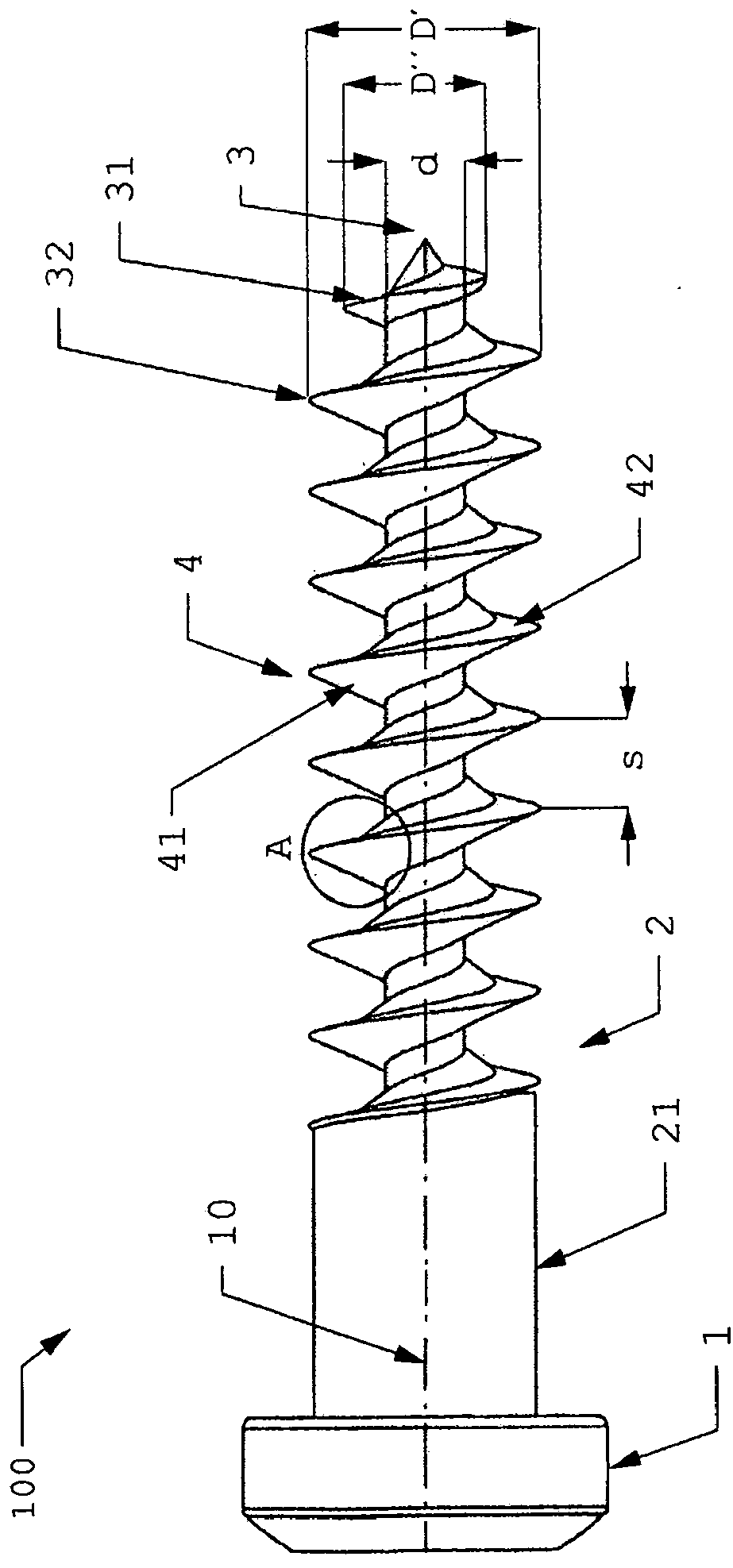
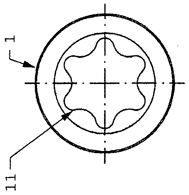
[0045] figure 1 An embodiment of a fastening element 100 according to the invention is shown, which has a fastening head 1 and a shank 2 which extends from the fastening head 1 in the direction of the main axis 10 and faces away from the The end of the fastening head 1 ends with a point 3 .

[0046] The length of the shank 2 extending from one end of the shank 2 , ie from the fastening head 2 up to the tip 3 , is preferably approximately 22 mm or approximately 25 mm.

[0047] The shank 2 has an external thread 4 over a portion of its extent in the direction of the main axis 10 . In the embodiment shown, the external thread 4 is a right-handed thread, ie the thread line rises to the right in a plan view of the thread and the fastening element is thus screwed into the material in a clockwise direction. In another embodiment, however, the external thread 4 can also be a left-handed thread which is screwed into the material in a counterclockwise direction.

[0048]The diameter ...


PUM

PropertyMeasurementUnit
lengthaaaaaaaaaa
densityaaaaaaaaaa
lengthaaaaaaaaaa

Abstract

Fastening element (100) for a porous material, in particular balsa wood, comprising a fastening head (1) designed to absorb torque in both directions of rotation about a main axis (10), and a shaft (2) which extends from the fastening head (1) and ends in a tip (3) at the end opposite the fastening head. The shaft (2) has an external thread (4) along at least part of its extension in the directionof the main axis (10) in order to be able to screw the fastening element (100) into the material.

Description

technical field [0001] The invention relates to a fastening element for porous materials and to the use of the fastening element. Background technique [0002] When using fastening elements in porous materials or cork, it must be taken into account that these materials have cavities in the interior and therefore there is only little loadable material in the surroundings of the external thread of the fastening element, so that the loadability of the material is restricted. [0003] If the fastening means known from the prior art, in particular screws, are used for porous materials, this often results in the screw breaking out of the material due to the material's low loadability and thus reduced force absorption. Contents of the invention [0004] In view of the known prior art, it is therefore an object to provide a fastening element which is suitable for use in porous materials as well as cork and which ensures a secure connection when screwed into these materials. [0...

Claims


Application Information

Patent Timeline
Patent Type & Authority Applications(China)
IPC IPC(8): F16B25/00
CPCF16B25/0015F16B25/0047
Inventor W·普菲斯特
Owner BOSSARD AG
Why Eureka
Try Eureka