Care bed for disabled elders
A nursing bed, elderly technology, applied in hospital beds, medical science, hospital equipment, etc., can solve the problem of increasing the nursing intensity of nursing staff, the solution of bending legs or toileting has not been well improved, and the comfort of patients has not been improved. and other problems, to achieve the effect of simple structure, reinforcement and stability, and reduction of labor intensity
- Summary
- Abstract
- Description
- Claims
- Application Information
AI Technical Summary
Problems solved by technology
Method used
Image

Examples
Embodiment Construction
[0021] The present invention is further described below in conjunction with accompanying drawing:
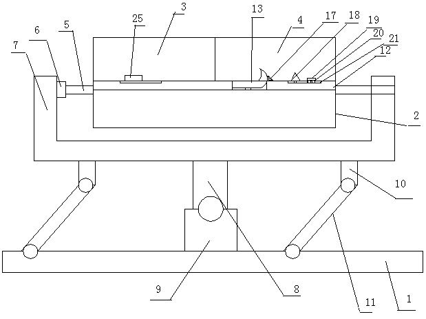
[0022]As shown in the accompanying drawings, a disabled elderly care bed is provided with a cylindrical bed and a bed support frame 1, and is characterized in that the cylindrical bed is composed of a bed bottom 2 and a bed cover, and the bed cover is composed of The upper body cover 3 on the left side and the lower body cover 4 on the right side are made up, and described upper body cover 3 is made as transparent shape, and lower body cover 4 is made as opaque shape, and described upper body cover 3 and lower body cover 4 are connected with bed respectively through hinge. The bottom 2 is connected, and the left and right sides of the bed bottom 2 are respectively provided with turning shafts 5, and the turning shafts 5 are fixedly connected with the bed bottom 2 respectively, and the turning shaft 5 on the left side is connected to the U-shaped front and rear turning motor 6 Th...
PUM
 Abstract
Description
Claims
Application Information
PatSnap Eureka turns technology decisions into work you can execute. Powered by our Innovation Knowledge Graph, it runs expert workflows across engineering, life sciences, materials and intellectual property. Get your review-ready output in minutes.


