Bridge drainage structure

A technology for drainage structures and bridges, used in bridges, bridge parts, bridge construction, etc., can solve the problems that the drainage holes are difficult to meet the requirements of rapid drainage, rapid drainage, and unsightly appearance of drainage holes.

Active Publication Date: 2019-06-21
齐齐哈尔市政工程设计研究院有限责任公司
View PDF11 Cites 4 Cited by
  • Summary
  • Abstract
  • Description
  • Claims
  • Application Information

AI Technical Summary

Problems solved by technology

And the pouring structure of this concrete guardrail will also cause rainwater drainage problems
Due to the closed sides, a large amount of rainwater accumulates in heavy rain. The traditional method adopts more than one drain hole on both sides of the bridge deck road, but this method is difficult to quickly drain the middle of the bridge deck, and the drainage area is relatively At the same time, opening a large number of weep holes is very unsightly in appearance, and it is difficult to meet the problem of rapid water drainage with fewer weep holes

Method used


Image

  • Bridge drainage structure
  • Bridge drainage structure
  • Bridge drainage structure

Examples


Embodiment Construction

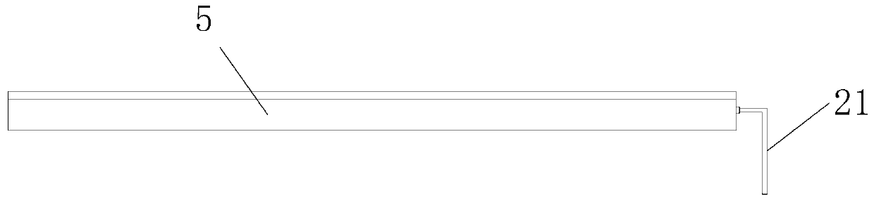
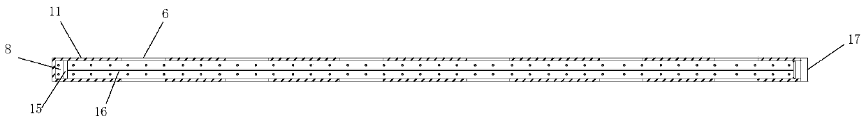
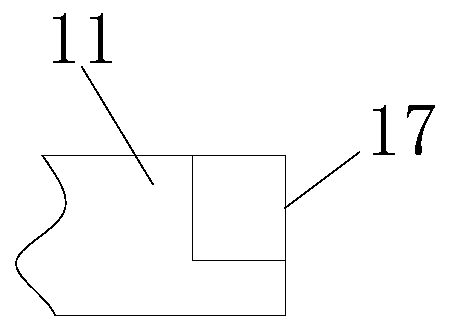
[0020] Such as Figure 4 As shown, the bridge drainage structure includes more than one buried box 5 embedded on the road surface of the bridge, the upper end surface of the buried box 5 is flush with the bridge surface, and the buried box 5 has a movable cavity 3 with an open top. , the movable chamber 3 is loaded into a raised portion 11 from top to bottom, and the raised portion 11 seals the top opening end of the entire movable chamber 3, and the raised portion 11 partially protrudes from the upper end surface of the buried box 5, and the raised portion More than one through groove 6 is opened on both sides of the top extension end of 11;

[0021] A filter screen 8 is arranged inside the raised part 11, and the filter screen 8 divides the inner chamber of the raised part 11 into an upper chamber 7 at the top and a lower chamber 1 at the bottom, and filter mesh holes are set on the filter screen 8 One side of the raised part 11 is facing the position of the upper chamber 7...


PUM


Abstract

The invention discloses a bridge drainage structure. The bridge drainage structure comprises one or more buried boxes embedded into a pavement of a bridge; the upper end faces of the buried boxes arearranged in parallel on the same level with bridge floor; a moving cavity with an opening on the top is formed inside each buried box; a convex part is mounted in each moving cavity from top to bottom; each convex part seals the opening end on the top of each whole moving cavity; Part of each convex part stretches out of the upper end face of the corresponding buried box; and one or more through grooves are respectively formed in two sides of the protrudent end on the top of each convex part. The drainage structure disclosed by the invention acts on a deceleration strip group arranged on the bridge; rainwater can be well intercepted; part of rainwater can be stored and discharged; a drainage structure is cancelled, so that the appearance is more attractive; the integrated structure designis more reasonable, and collected water can be utilized for realizing buffering and dust falling effects.

Description

technical field [0001] The invention relates to the field of bridges, in particular to a bridge drainage structure. Background technique [0002] Both sides of the bridge deck are blocked by bridge deck guardrails. The current guardrails are formed by pouring concrete to increase the overall impact resistance, which can well protect vehicles from breaking through the guardrails during impact. The pouring structure of this concrete guardrail will also cause rainwater drainage problems. Due to the closed sides, a large amount of rainwater accumulates in heavy rain. The traditional method adopts more than one drain hole on both sides of the bridge deck road, but this method is difficult to quickly drain the middle of the bridge deck, and the drainage area is relatively However, it is very unattractive to open a large number of scuppers in appearance, and it is difficult to meet the problem of fast drainage with less scuppers. Contents of the invention [0003] The technical...

Claims


Application Information

Patent Timeline
Patent Type & Authority Applications(China)
IPC IPC(8): E01D19/08
Inventor 郭文
Owner 齐齐哈尔市政工程设计研究院有限责任公司
Why Eureka
Try Eureka