Cooling equipment for tool with high heat intensity

A high-strength and tool technology, applied in lighting and heating equipment, household heating, heating methods, etc., can solve the problems of inability to increase the wind power of the airflow meter, no setting, and inability to protect the internal components of the airflow meter, so as to avoid malfunctions. Inhalation of dust, safe and convenient use, scientific and reasonable structure

Inactive Publication Date: 2019-06-21
西安天恩电子科技有限公司
View PDF0 Cites 0 Cited by
  • Summary
  • Abstract
  • Description
  • Claims
  • Application Information

AI Technical Summary

Problems solved by technology

[0004] The present invention provides a heat-reducing device for a tool with high thermal intensity, which can effectively solve the problem that there is no driving shaft and ring-shaped omni-directional fixer in the above-mentioned background technology, which is inconvenient for users to push and pull the air flow meter, and there is no metal thin wire braided isolation Objects and stable rods cannot protect the internal components of the airflow meter, there is no soft plastic channel, the outlet direction of the airflow meter cannot be adjusted, and two sheet rolling machines are not installed, so the wind force of the airflow meter cannot be increased

Method used


Image

  • Cooling equipment for tool with high heat intensity
  • Cooling equipment for tool with high heat intensity
  • Cooling equipment for tool with high heat intensity

Examples


Embodiment Construction

[0019] The preferred embodiments of the present invention will be described below in conjunction with the accompanying drawings. It should be understood that the preferred embodiments described here are only used to illustrate and explain the present invention, and are not intended to limit the present invention.

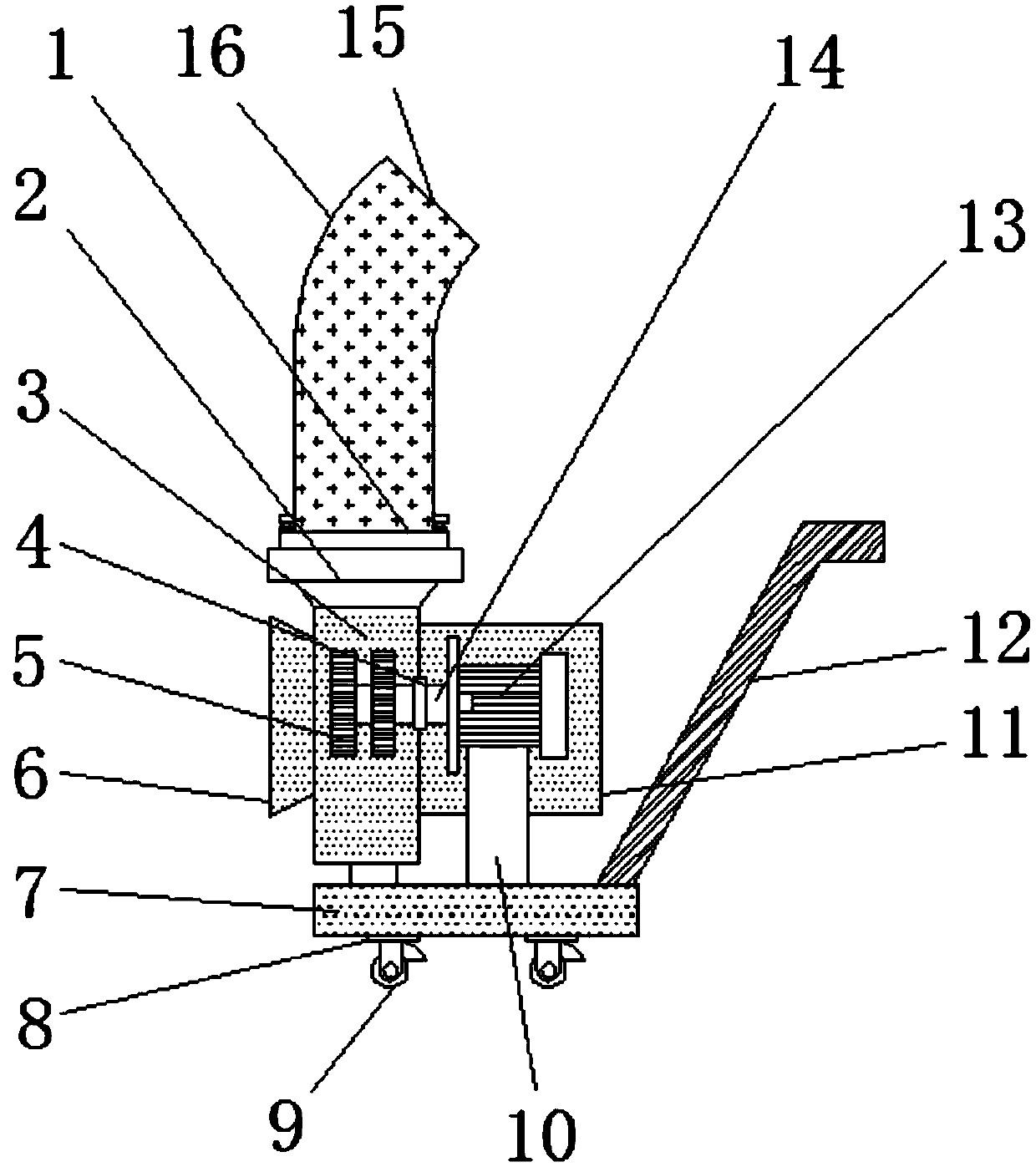
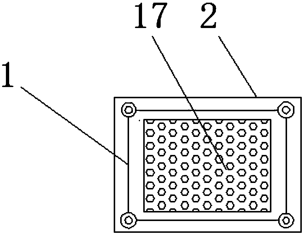
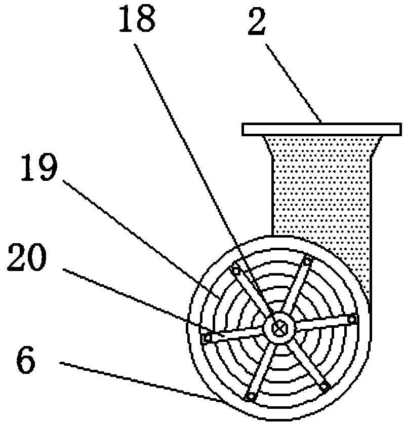
[0020] Example: such as Figure 1-4 As shown, the present invention provides a technical solution, a cooling device for a tool with high thermal intensity, including a thin metal plate 1, a primary output terminal 2, an air flow meter 3, a rotary rod 4, a sheet rolling machine 5, an inlet 6, Base 7, Firm Base 8, Ring Omnidirectional Fixer 9, Contact Rod 10, Anti-Travel Film 11, Drive Shaft 12, Energy Consumption Motor 13, Metal Ring Slider 14, Secondary Output 15, Soft Plastic Channel 16, small hole 17, metal crown rotating object 18, thin metal wire braided spacer 19 and firm bar 20, the upper end of base 7 is provided with contact bar 10, and the lower end of base...


PUM


Abstract

The invention discloses cooling equipment for a tool with high heat intensity. The cooling equipment comprises an airflow meter, a rotary rod, sheet rolling machines, a loss prevention film, a drive shaft, an energy consumption motor, a metal ring slider, a soft plastic channel, a metal crown rotating body, a metal fine wire braiding spacer and a stabilizer bar; the lower end of a stabilizer substrate is provided with an annular omnidirectional fixer; one side of a contact bar is provided with the drive shaft; the energy consumption motor is mounted in the loss prevention film; one end of theenergy consumption motor is provided with the metal ring slider; the rotary rod is arranged at the joint of the energy consumption motor and the airflow meter; one side of the rotary rod is provided with a sheet rolling machine; and the upper end of a metal sheet is provided with the soft plastic channel. The cooling equipment is scientific in structure and safe and reliable to use, by arranging the drive shaft and the annular omnidirectional fixer, a user can start the airflow meter conveniently and does not need to use excessive energy for transportation, by arranging the metal fine wire braiding spacer and the stabilizer bar, internal components of the airflow meter can be protected, by forming the soft plastic channel, the outlet direction of the airflow meter can be adjusted, unidirectional discharge of the airflow meter is avoided, and the horsepower of the airflow meter can be greatly increased by arranging the two sheet rolling machines.

Description

technical field [0001] The invention relates to the technical field of a high-temperature-resistant gas flow meter for a furnace, in particular to a heat-reducing device for a tool with high thermal intensity. Background technique [0002] The air flow meter is not only used in various traditional national economic fields and ventilation in various public places, but also in various new technical fields, and the technical prospect is just around the corner. [0003] However, the air flow meters with high thermal intensity at the present stage not only have few functions and complicated structures, but also have low efficiency and safety performance. Contents of the invention [0004] The present invention provides a heat-reducing device for a tool with high thermal intensity, which can effectively solve the problem that there is no driving shaft and ring-shaped omni-directional fixer in the above-mentioned background technology, which is inconvenient for users to push and ...

Claims


Application Information

Patent Timeline
Patent Type & Authority Applications(China)
IPC IPC(8): F24F7/06F24F3/16F24F13/02F24F13/28F24F13/32
Inventor 张勇
Owner 西安天恩电子科技有限公司
Why Eureka
Try Eureka