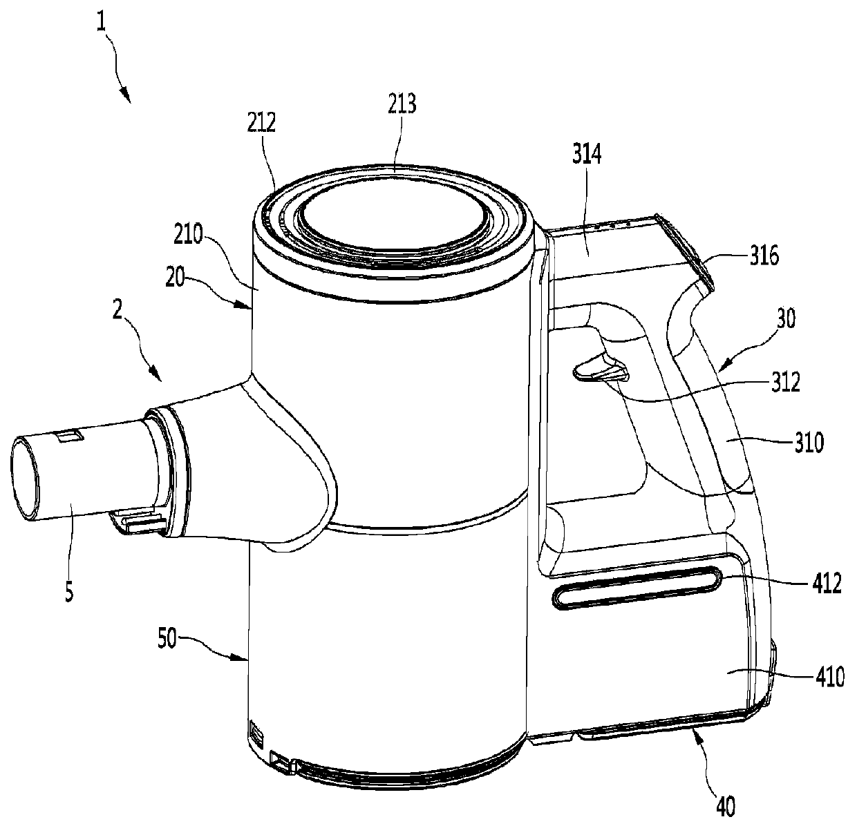
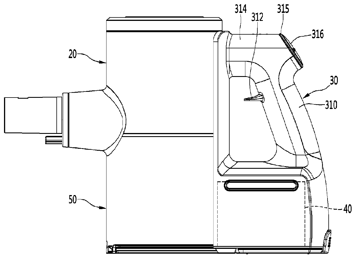
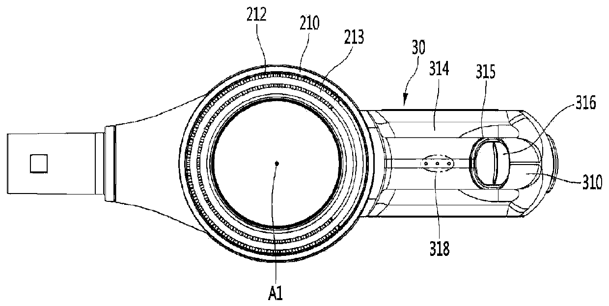
Vacuum cleaner

A technology for vacuum cleaners and suction parts, which is applied in the direction of vacuum cleaners, suction filters, handles, etc. It can solve problems such as excessive force on the wrist, flow loss, and inconvenient use of portable vacuum cleaners, and achieve the effect of preventing burden and small flow loss

Active Publication Date: 2019-07-12
LG ELECTRONICS INC
View PDF10 Cites 0 Cited by
  • Summary
  • Abstract
  • Description
  • Claims
  • Application Information

AI Technical Summary

Problems solved by technology

[0009] According to the existing literature, the heavy airflow generator is arranged directly above the handle, and the heavy power supply is arranged directly below the handle. Inconvenient when using a hand-held vacuum cleaner, there is a problem of excessive force on the wrist
[0010] In addition, according to the existing literature, the airflow generator is arranged behind the centrifugal separation device, thereby the flow path for guiding the air from the centrifugal separation device to the airflow generator becomes longer, and the flow direction of the air discharged from the centrifugal separation device changes. In the state of flow to the airflow generator, there is a problem of flow loss
[0011] In addition, according to the existing literature, the airflow generator is arranged directly above the handle, so there is a problem that the air discharged from the airflow generator is directly discharged to the arm holding the handle

Method used


Image

  • Vacuum cleaner
  • Vacuum cleaner
  • Vacuum cleaner

Examples


Embodiment Construction

[0071] Hereinafter, some embodiments of the present invention will be described in detail with exemplary drawings. It should be noted that when assigning reference signs to constituent elements in each drawing, the same reference numerals are used as much as possible even if the same constituent elements appear in different drawings. In addition, when describing the embodiments of the present invention, when it is judged that the specific description of related known structures or functions hinders the understanding of the embodiments of the present invention, the detailed description will be omitted.

[0072] In addition, terms such as first, second, A, B, (a), and (b) may be used when describing constituent elements of the embodiments of the present invention. These terms are only used to distinguish this structural element from other structural elements, and the nature, sequence, sequence, etc. of the corresponding structural elements are not limited by the terms. When it ...


PUM


Abstract

A vacuum cleaner comprises the components of a body which has a suctionpart that is arranged at the front part of the body and is used for sucking dust-containing air; a handle which is arranged at the opposite side of the suction part of the body and is held by a user; wherein the vacuum cleaner further comprises a battery housing which is arranged at the lower side of the handle and has a battery accommodating space that is surrounded by side walls and forms an appearance and forms a lower opening, thereby enabling the battery to be accommodated in the battery accommodating space separatelyfrom the opening.

Description

[0001] This application is a divisional application with the application number 201780020238.2 and the application date of March 31, 2017 as the parent application. technical field [0002] The present invention relates to vacuum cleaners. Background technique [0003] Vacuum cleaners can be divided into: manual vacuum cleaners, in which the user directly moves the vacuum cleaner to perform cleaning; automatic vacuum cleaners, in which the vacuum cleaner travels and performs cleaning by itself. [0004] And, the manual vacuum cleaner may be classified into a canister vacuum cleaner, an upright vacuum cleaner, a hand-held vacuum cleaner, a stick-type vacuum cleaner, and the like according to the shape of the vacuum cleaner. [0005] A portable vacuum cleaner is disclosed in Korean Patent Publication No. 10-1127088 (authorized date: March 8, 2012), which is a prior document. [0006] The portable vacuum cleaner includes a suction pipe, an airflow generator, a centrifugal sepa...

Claims


Application Information

Patent Timeline
Patent Type & Authority Applications(China)
IPC IPC(8): A47L9/28A47L9/32A47L9/16
CPCA47L9/2884A47L9/16A47L9/1683A47L9/322A47L5/24A47L9/00A47L9/1625A47L9/1641A47L9/22A47L9/1608A47L9/12A47L9/2857Y02E60/10A47L9/32A47L5/28A47L9/149A47L9/1616A47L9/2842
Inventor 南普铉黄正培金真珠金南希安贤贞
Owner LG ELECTRONICS INC
Why Eureka
Try Eureka