Electronic equipment patch jig and manufacturing method thereof

A technology of electronic equipment and manufacturing method, which is applied in branch office equipment, telephone communication, electrical components, etc., can solve the problems of glass protection sheet deviation, affect product appearance and performance, and cannot guarantee the lamination accuracy, so as to reduce the lamination error , Guarantee the effect of product appearance and performance

Inactive Publication Date: 2019-07-12
YONGZHOU FUXING ELECTRONICS SCI & TECH
View PDF7 Cites 2 Cited by
  • Summary
  • Abstract
  • Description
  • Claims
  • Application Information

AI Technical Summary

Problems solved by technology

However, in the production process of electronic equipment, at present, the glass protection sheet is directly attached to the main body of the electronic equipment by manual means, and the lamination accuracy cannot be guaranteed, resulting in the deviation of the glass protection sheet of some electronic equipment, which affects Product appearance and performance

Method used


Image

  • Electronic equipment patch jig and manufacturing method thereof
  • Electronic equipment patch jig and manufacturing method thereof
  • Electronic equipment patch jig and manufacturing method thereof

Examples


Embodiment Construction

[0016] The principles and features of the present invention are described below in conjunction with the accompanying drawings, and the examples given are only used to explain the present invention, and are not intended to limit the scope of the present invention.

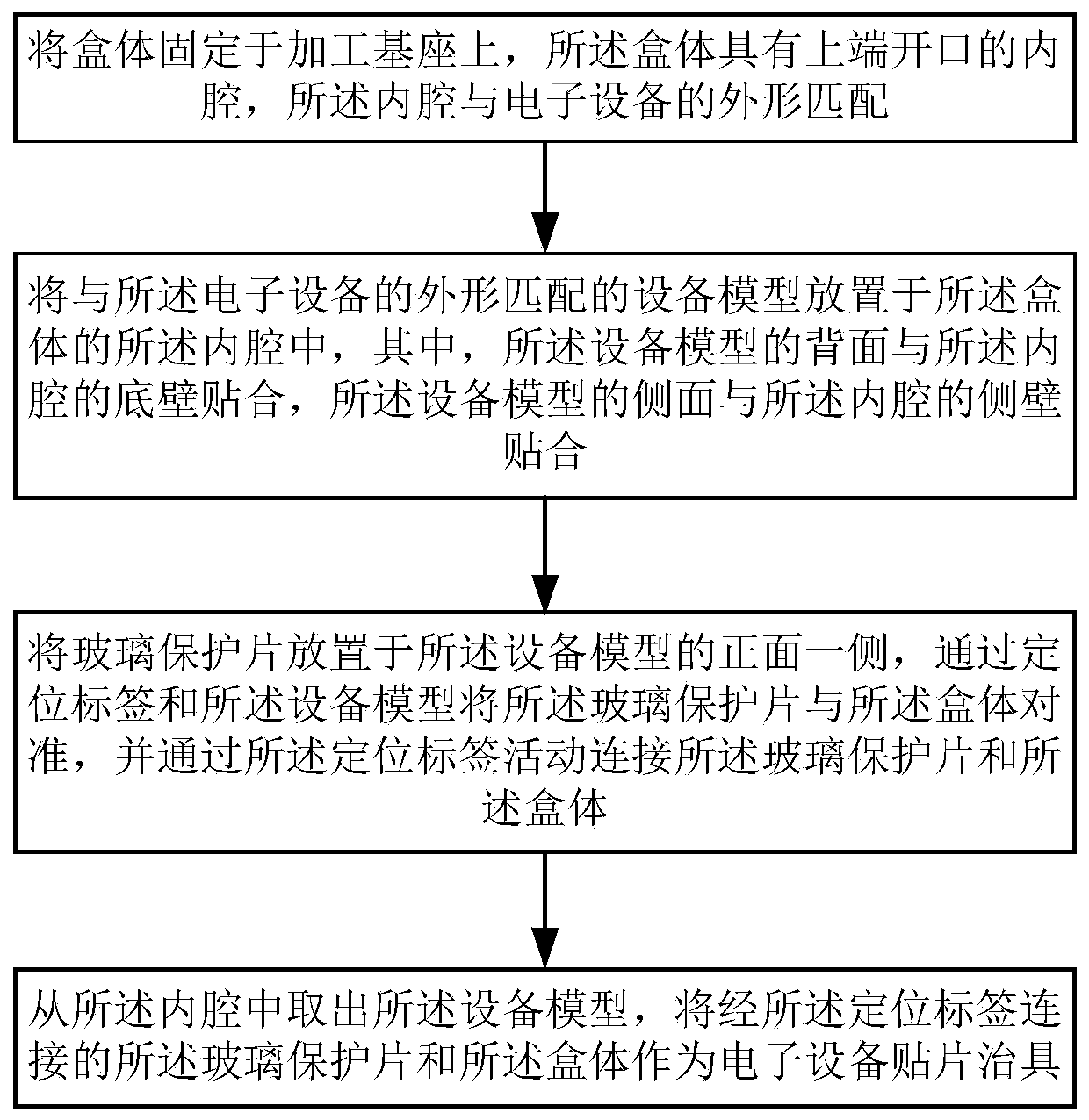
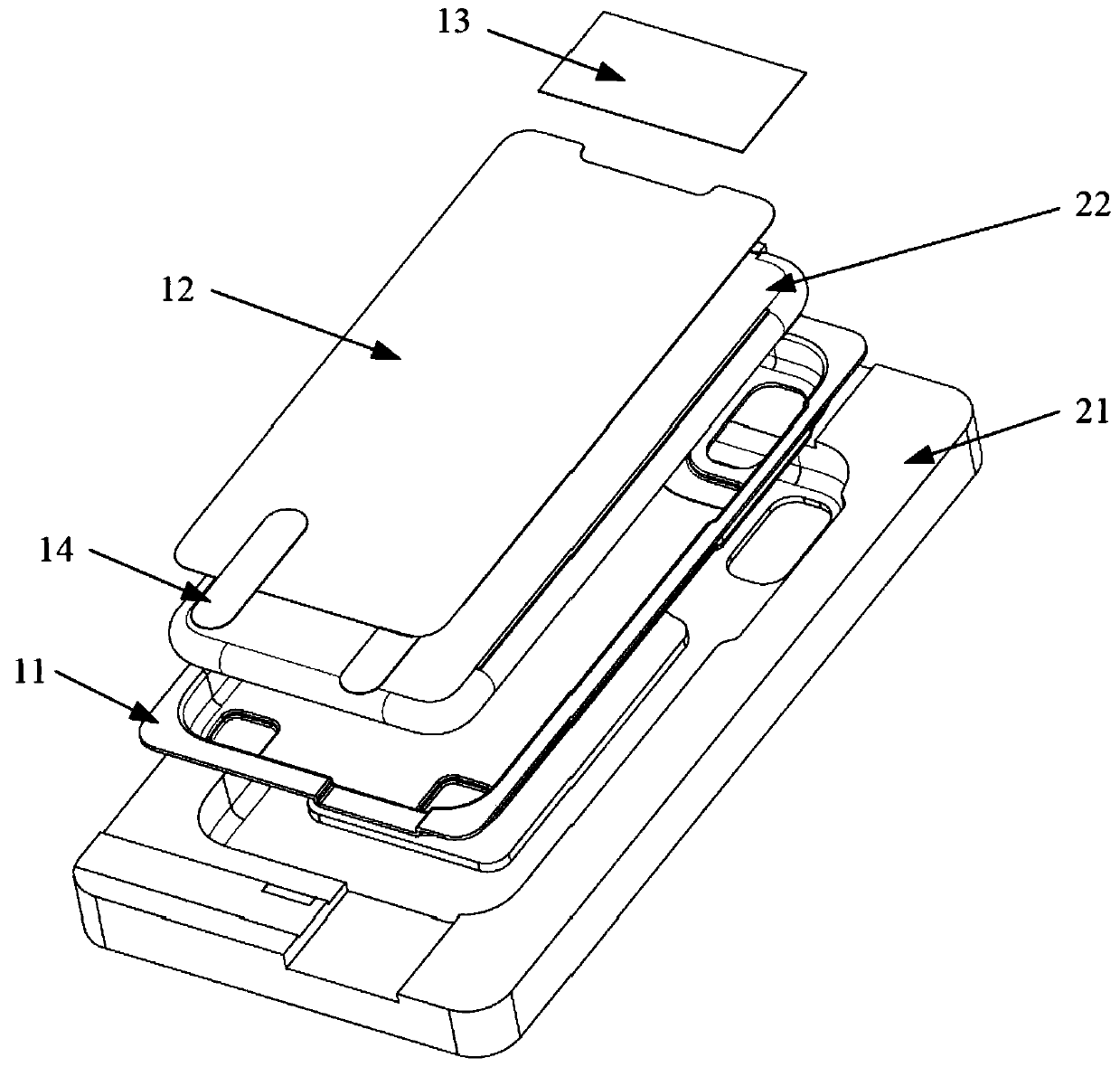
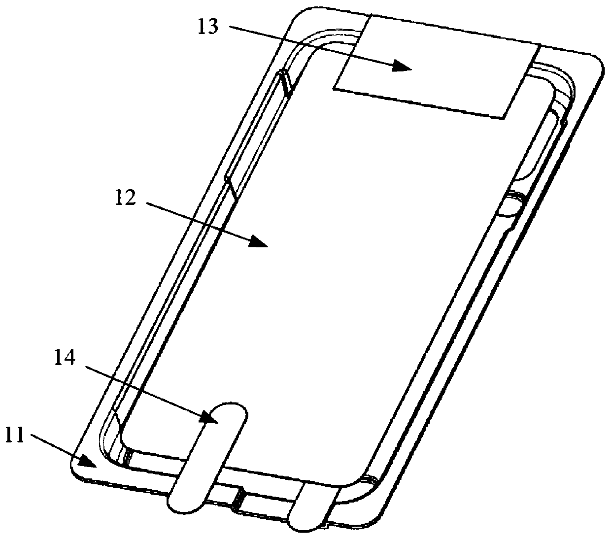
[0017] Such as figure 1 and figure 2 As shown, a method for manufacturing an electronic device patch fixture provided by an embodiment of the present invention includes the following steps:

[0018] The box body 11 is fixed on the processing base 21. The box body 11 has an inner cavity with an open upper end, and the inner cavity matches the shape of the electronic device.

[0019] Specifically, the inner cavity of the box body 11 can be formed by, for example, compression molding, and the inner cavity matches the shape of the electronic device to be mounted. For example, if the electronic device is a mobile phone, and its shape is a rounded rectangle, the inner cavity also is the same rounded rectangle. It shou...


PUM


Abstract

The invention relates to an electronic equipment patch jig and a manufacturing method thereof. The manufacturing method comprises the following steps that a box body is fixed on a processing base, wherein the box body is provided with an inner cavity with an open upper end, and the inner cavity is matched with the appearance of electronic equipment; an equipment model matched with the appearance of the electronic equipment is placed in the inner cavity of the box body, wherein the back surface of the equipment model is attached to the bottom wall of the inner cavity, and the side surface of the equipment model is attached to the side wall of the inner cavity; a glass protection sheet is placed on one side of the front surface of the equipment model, the glass protection sheet is aligned with the box body through a positioning label and the equipment model, and the glass protection sheet is movably connected with the box body through the positioning label; and the equipment model is taken out from the inner cavity, and the glass protection sheet and the box body connected by the positioning label are used as the electronic equipment patch jig. According to the technical scheme, thebonding error of the protection sheet can be reduced, and the product appearance and performance of the electronic equipment such as mobile phones are ensured.

Description

technical field [0001] The invention relates to the technical field of fixture processing, in particular to a patch fixture for electronic equipment and a manufacturing method thereof. Background technique [0002] Intelligent electronic devices such as smartphones, smart watches or tablet computers are widely used in all aspects of people's lives, and the front of the display usually has a layer of glass protection. However, in the production process of electronic equipment, at present, the glass protection sheet is directly attached to the main body of the electronic equipment by manual means, and the lamination accuracy cannot be guaranteed, resulting in the deviation of the glass protection sheet of some electronic equipment, which affects Product appearance and performance. Contents of the invention [0003] Aiming at the deficiencies of the prior art, the present invention provides an electronic device patch jig and a manufacturing method thereof. [0004] In one a...

Claims


Application Information

Patent Timeline
IPC IPC(8): G09F9/30H04M1/02
CPCG09F9/30H04M1/026
Inventor 易广健杨子兵
Owner YONGZHOU FUXING ELECTRONICS SCI & TECH
Why Eureka
Try Eureka