Remote pipe local annular repair equipment and method

A pipeline and local technology, which is applied in the field of remote pipeline partial annular repair equipment and its repair field, can solve the problems of increasing maintenance costs, uneven repair surface, and affecting the quality of repair.

Active Publication Date: 2019-07-19
浙江蓝清市政建设集团有限公司
View PDF9 Cites 7 Cited by
  • Summary
  • Abstract
  • Description
  • Claims
  • Application Information

AI Technical Summary

Problems solved by technology

The above-mentioned three schemes all use different methods to repair the parts inside the pipeline, but they do not explain how to perform operations on the pipeline before repairing, because the inner wall of the pipeline will have different degrees of dirt and rust due to long-term use If these are not cleaned, the quality of the repair will be affected, which will lead to poor quality of the repair medium, the repair surface is not smooth, and it is very likely to form air bubbles or pores, which will lead to secondary repairs in a short period of time, which will increase maintenance cost

Method used


Image

  • Remote pipe local annular repair equipment and method
  • Remote pipe local annular repair equipment and method
  • Remote pipe local annular repair equipment and method

Examples


Embodiment Construction

[0046] A number of embodiments of the present invention will be disclosed in the following figures. For the sake of clarity, many practical details will be described together in the following description. It should be understood, however, that these practical details should not be used to limit the invention. That is, in some embodiments of the invention, these practical details are not necessary. In addition, for the sake of simplifying the drawings, some well-known and commonly used structures and components will be shown in a simple schematic manner in the drawings.

[0047] In addition, in the present invention, descriptions such as "first", "second" and so on are used for description purposes only, and do not refer to the meaning of order or sequence, nor are they used to limit the present invention, but are only for the purpose of distinguishing the following The components or operations described by the same technical terms are only used, but should not be understood a...


PUM


Abstract

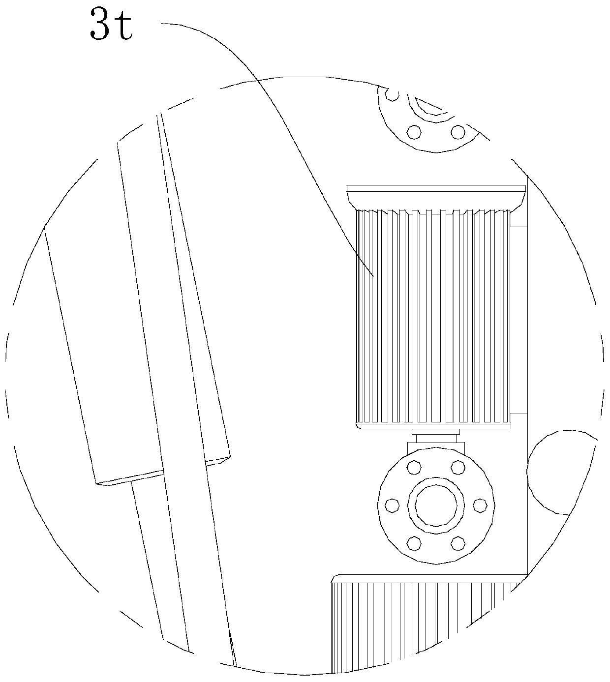
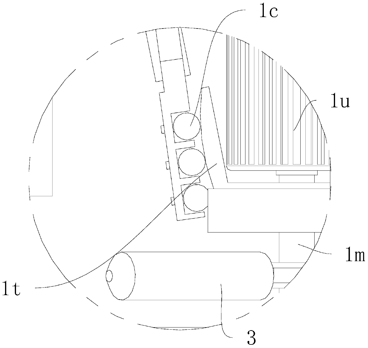
The invention relates to the technical field of pipe maintenance equipment, in particular, remote pipe local annular repair equipment and method. The remote pipe local annular repair equipment comprises a detection mechanism, a repair mechanism, an auxiliary mechanism and two small-size intelligent vehicles. The detection mechanism and the repair mechanism are each arranged on the corresponding small-size intelligent vehicle. Each small-size intelligent vehicle comprises a base plate, a lifting plate, an ascending-and-descending block and a small-size hydraulic rod. One end of each lifting plate is in shaft connection with one end of the corresponding base plate in a matched manner. Each small-size hydraulic rod is mounted at the outer side of the corresponding base plate and used for driving the other end of the corresponding lifting plate to move. A top beam bracket is arranged above each base plate in an erected manner. Each ascending-and-descending block is movably arranged at oneend of the corresponding top beam bracket. The bottom of each ascending-and-descending block is in transmission fit with the free end of the corresponding lifting plate. The detection mechanism comprises a CCD camera and a light supplementing device, wherein the CCD camera and the light supplementing device are mounted at the front sides of the ascending-and-descending blocks corresponding to theCCD camera and the light supplementing device. The repair mechanism comprises a first spray head, a second spray head and a third spray head, wherein the first spray head, the second spray head and the third spray head are mounted at the front sides of the ascending-and-descending blocks corresponding to the first spray head, the second spray head and the third spray head. The auxiliary mechanismcomprises a cleaning air bag and a compaction air bag. By means of the remote pipe local annular repair equipment and method, the repair quality can be greatly improved.

Description

technical field [0001] The present invention relates to the technical field of pipeline maintenance equipment, in particular to a remote pipeline partial annular repair equipment and a repair method thereof. Background technique [0002] With the continuous acceleration of the urbanization process, urban underground pipelines have become intricate and complicated. After a large number of buried pipelines have been put into operation for several years, various problems will inevitably occur, such as cracks, deformation, and internal rupture and leakage due to corrosion. In order to ensure the normal operation of the pipe network, it is necessary to replace or repair the problematic pipe sections. The simplest repair method is excavation and replacement, excavating from the road surface to the pipeline, and directly replacing the corresponding prefabricated pipe. However, this method has high construction costs, and it is not worthwhile to perform this operation for the damag...

Claims


Application Information

Patent Timeline
Patent Type & Authority Applications(China)
IPC IPC(8): F16L55/1645F16L55/18F16L55/28F16L101/30
CPCF16L55/1645F16L55/18F16L55/28F16L2101/30
Inventor 陈斌辉丁海勇张荣章利梁易南兵
Owner 浙江蓝清市政建设集团有限公司
Why Eureka
Try Eureka