
External controller of decorative lamp

A technology of controllers and lamps, applied in the field of controllers, can solve problems such as damage, unfavorable replacement and maintenance, and complicated installation

Inactive Publication Date: 2019-07-19
泸州王家机械设备有限公司
View PDF0 Cites 0 Cited by
  • Summary
  • Abstract
  • Description
  • Claims
  • Application Information

AI Technical Summary

Problems solved by technology

[0002] All kinds of decorative lamps have been popularized in daily life and have long become a must for high-end home decoration. However, most of the various decorative lamps use LED tubes or light strips to emit light. After connecting the 220V mains power to the lamps, various transformers are required The power board or segmental switch is used for control. The existing technology is to place various variable voltage power boards or segmental switches on the bottom plate of the lamp near the roof of the room, and install various lamp accessories in sequence from top to bottom. , because most of the existing decorative lamps are lamps with miniature crystal accessories, there are many accessories, and the installation is complicated. When the transformer power board or segment switch of the lamp is damaged and needs to be replaced in the later stage, the accessories on the lamp need to be removed one by one and opened. The replacement operation can only be done after the base plate of the lamp, and there are many power boards of the lamp, all of which are 4 to 6 groups. Such a cumbersome operation requires a large amount of work, time-consuming and labor-intensive, and is easy to cause damage to the accessories, which is not conducive to later replacement and maintenance.

Method used


Image

  • External controller of decorative lamp
  • External controller of decorative lamp
  • External controller of decorative lamp

Examples


Embodiment Construction

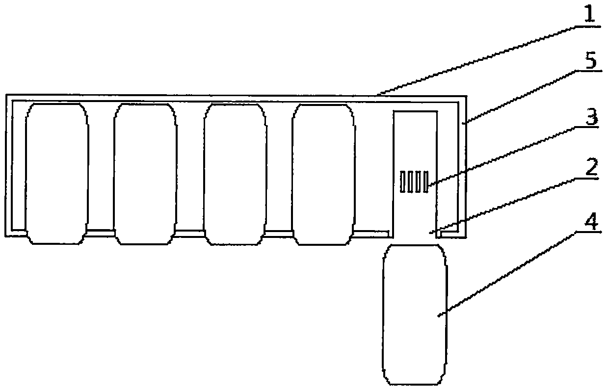
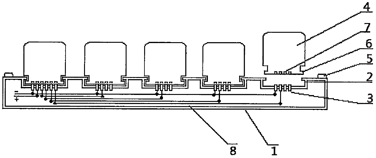
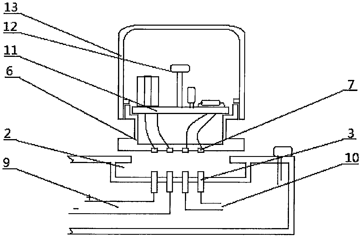
[0010] pass figure 1 It can be seen that the external controller is composed of a base and a light-emitting panel box. The base (1) is a cuboid, and the back is installed on the roof of the room outside the lamp or inside the lamp with bolts. Combine the combination groove (2), the inside of the combination groove is provided with a conductive reed (3), the bottom of the light-emitting panel box (4) is provided with a combination seat, the combination seat is provided with a conductive electrode, the combination seat and the combination groove (2) When the combination seat on the light-emitting panel box (4) is inserted into the combination groove (2), the conductive reed (3) keeps in contact with the conductive electrode, and the power supply of the base can be input by the conductive reed and the conductive electrode The light-emitting electric board box is provided with light-emitting light strips (5) around the periphery of the base.

[0011] pass figure 2 It can be see...


PUM


Abstract

The invention relates to a controller of a decorative lamp, in particular to a control circuit board for lamp voltage transformation. An external controller of the decorative lamp is composed of two parts of a base, and light-emitting circuit board boxes, combining grooves are formed in the base, a conductive reed is arranged in each combining groove, a lamp strip is arranged all around the periphery of the base, a light gathering box is arranged on each light-emitting circuit board box, the bottom of each light gathering box is connected with a combining base, a voltage transformation power board or a sectional switch power board is arranged inside each light gathering box, an LED lamp bead is arranged at the top end of each circuit board, a conductive electrode is arranged at the bottomof each combining base, the conductive electrodes are connected with the circuit boards through wires, the wire inlet end of each conductive reed is connected with a mains supply through a wire, and the wire outlet end of each conductive reed is connected with the lamp strip or the lamp bead of the lamp. The external controller is arranged on the outer side of the lamp or the inner surface of theopen type lamp, when the voltage transformation power board of the lamp or the sectional switch power board is damaged, the light-emitting circuit board box needing to be replaced can be taken out ofthe base, the normal light-emitting circuit board box is inserted into the base, and thus the replacement is completed.

Description

technical field [0001] The invention relates to a controller of a decorative lamp, in particular to a control circuit board used for voltage transformation of the lamp. Background technique [0002] All kinds of decorative lamps have been popularized in daily life and have long become a must for high-end home decoration. However, most of the various decorative lamps use LED tubes or light strips to emit light. After connecting the 220V mains power to the lamps, various transformers are required The power board or segmental switch is used for control. The existing technology is to place various variable voltage power boards or segmental switches on the bottom plate of the lamp near the roof of the room, and install various lamp accessories in sequence from top to bottom. , because most of the existing decorative lamps are lamps with miniature crystal accessories, there are many accessories, and the installation is complicated. When the transformer power board or segment switc...

Claims


Application Information

Patent Timeline
Patent Type & Authority Applications(China)
IPC IPC(8): F21V23/00F21V23/06F21Y115/10
CPCF21V23/003F21V23/004F21V23/06F21Y2115/10
Inventor 王明中
Owner 泸州王家机械设备有限公司
Learn More