Wastewater treatment plant water inlet floating garbage salvage machine

A technology for waste water treatment and water inlet, which is applied in the direction of open water surface cleaning, water conservancy engineering, construction, etc., can solve the problems of low work efficiency and trouble, and achieve the effect of improving work efficiency.

Active Publication Date: 2019-07-26
青岛胶州北控水务有限公司
View PDF8 Cites 7 Cited by
  • Summary
  • Abstract
  • Description
  • Claims
  • Application Information

AI Technical Summary

Problems solved by technology

[0003] In order to overcome the shortcomings of the staff taking small boats and then salvaging floating garbage with fishing tools, which is troublesome and has low work efficiency, the technical problem to be solved is: to provide a waste water treatment plant that is relatively simple and can improve work efficiency Inlet Floating Garbage Salvage Machine

Method used


Image

  • Wastewater treatment plant water inlet floating garbage salvage machine
  • Wastewater treatment plant water inlet floating garbage salvage machine
  • Wastewater treatment plant water inlet floating garbage salvage machine

Examples


Embodiment 1

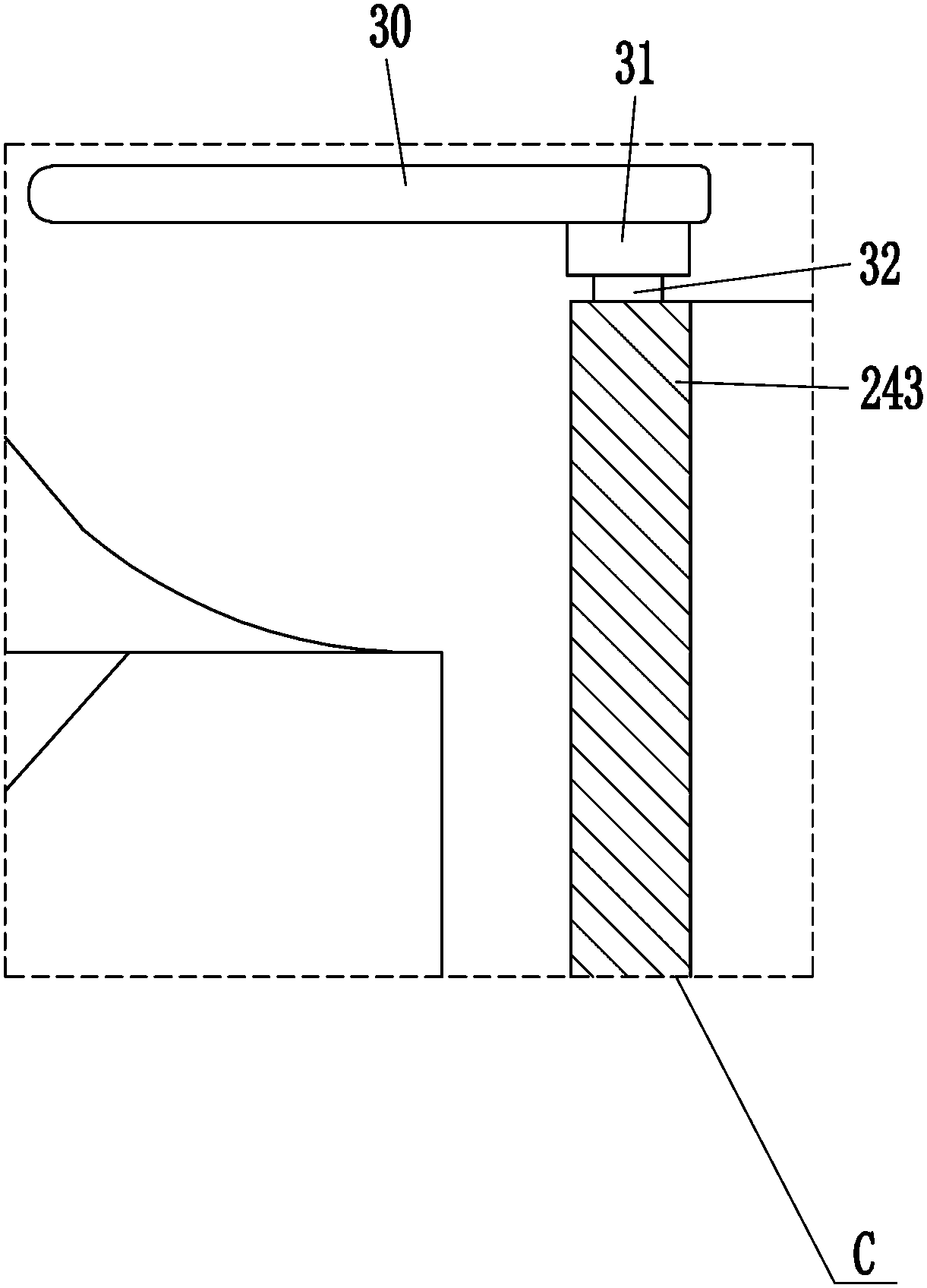
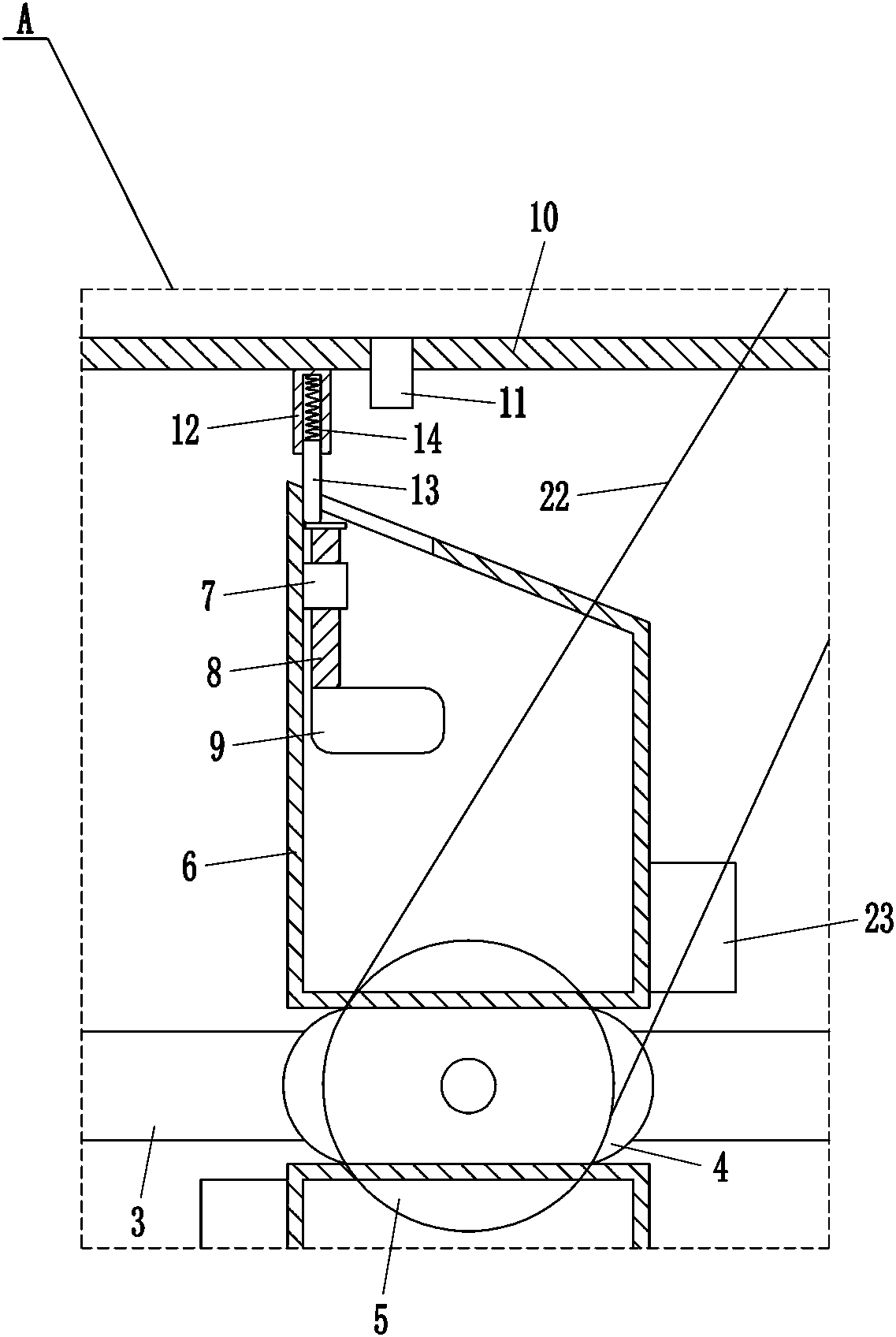
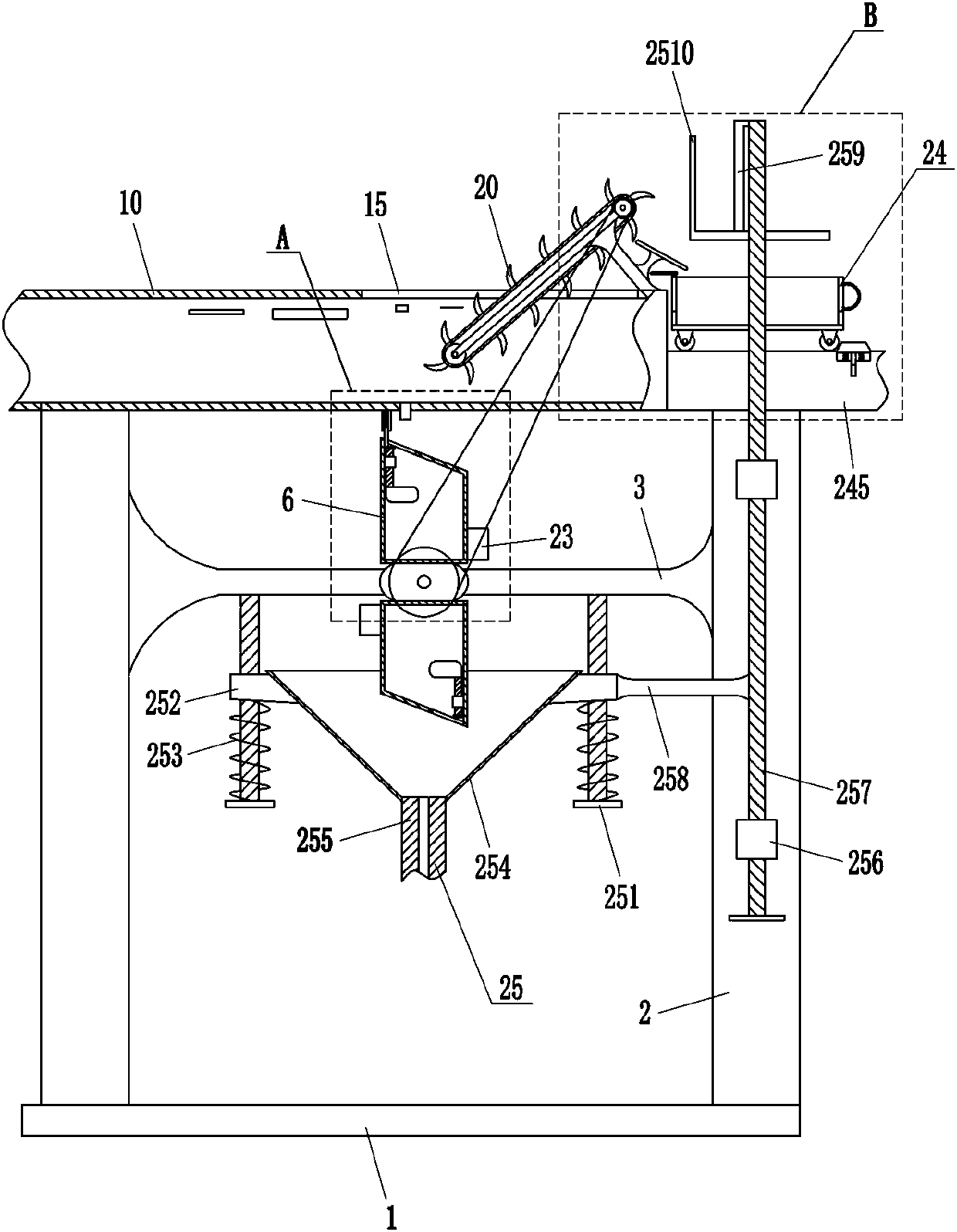
[0022] A waste water treatment plant water inlet floating garbage salvage machine, such as Figure 1-4As shown, it includes bottom plate 1, support rod 2, cross bar 3, oval block 4, large pulley 5, box body 6, guide sleeve 7, guide rod 8, floating block 9, water inlet pipe 10, small water pipe 11, sleeve 12. Sleeve rod 13, first spring 14, inclined plate 16, mounting plate 17, conveying roller 18, conveying belt 19, lever 20, small pulley 21, flat belt 22, weight 23 and collecting mechanism 24, bottom plate 1 top The left and right sides are connected with support rods 2, and the upper part between the two support rods 2 is connected with a cross bar 3, and the middle part of the front side of the cross bar 3 is rotatably equipped with an ellipse block 4, and the front side of the ellipse block 4 is equipped with a large belt pulley 5. There are two water-filled tanks 6, which are respectively arranged on the upper and lower sides of the ellipse block 4. The upper left side of...

Embodiment 2

[0024] A waste water treatment plant water inlet floating garbage salvage machine, such as Figure 1-4 As shown, it includes bottom plate 1, support rod 2, cross bar 3, oval block 4, large pulley 5, box body 6, guide sleeve 7, guide rod 8, floating block 9, water inlet pipe 10, small water pipe 11, sleeve 12. Sleeve rod 13, first spring 14, inclined plate 16, mounting plate 17, conveying roller 18, conveying belt 19, lever 20, small pulley 21, flat belt 22, weight 23 and collecting mechanism 24, bottom plate 1 top The left and right sides are connected with support rods 2, and the upper part between the two support rods 2 is connected with a cross bar 3, and the middle part of the front side of the cross bar 3 is rotatably equipped with an ellipse block 4, and the front side of the ellipse block 4 is equipped with a large belt pulley 5. There are two water-filled tanks 6, which are respectively arranged on the upper and lower sides of the ellipse block 4. The upper left side o...

Embodiment 3

[0027] A waste water treatment plant water inlet floating garbage salvage machine, such as Figure 1-4 As shown, it includes bottom plate 1, support rod 2, cross bar 3, oval block 4, large pulley 5, box body 6, guide sleeve 7, guide rod 8, floating block 9, water inlet pipe 10, small water pipe 11, sleeve 12. Sleeve rod 13, first spring 14, inclined plate 16, mounting plate 17, conveying roller 18, conveying belt 19, lever 20, small pulley 21, flat belt 22, weight 23 and collecting mechanism 24, bottom plate 1 top The left and right sides are connected with support rods 2, and the upper part between the two support rods 2 is connected with a cross bar 3, and the middle part of the front side of the cross bar 3 is rotatably equipped with an ellipse block 4, and the front side of the ellipse block 4 is equipped with a large belt pulley 5. There are two water-filled tanks 6, which are respectively arranged on the upper and lower sides of the ellipse block 4. The upper left side o...


PUM


Abstract

The invention relates to a salvage machine, in particular to a wastewater treatment plant water inlet floating garbage salvage machine. According to the wastewater treatment plant water inlet floatinggarbage salvage machine, the wastewater treatment plant water inlet floating garbage salvage machine is relatively simple and can improve the working efficiency. According to the technical scheme, the wastewater treatment plant water inlet floating garbage salvage machine comprises a bottom plate, supporting rods, a cross rod, an elliptical block, a large belt pulley, a box body and the like; andthe supporting rods are connected to the left side and the right side of the top of the bottom plate, the cross rod is connected to the upper part between the two supporting rods, and the ellipticalblock is rotatably mounted in the middle of the front side of the cross rod. The wastewater treatment plant water inlet floating garbage salvage machine can continuously salvage floating garbage through a driving lever, therefore, simpler and more convenient are achieved, and the working efficiency can be improved; and the floating garbage in a gathering vehicle can be compressed through a compression mechanism, so that wastewater residual in the floating garbage can be better discharged through a screen, and the gathering vehicle can enabled to accommodate more floating garbage.

Description

technical field [0001] The invention relates to a salvage machine, in particular to a salvage machine for floating garbage at the water inlet of a waste water treatment plant. Background technique [0002] Wastewater refers to the water discharged during people's activities. In order to avoid the waste water from polluting the environment, the waste water needs to be treated. In order to better treat the waste water, it is necessary to salvage the floating garbage in the waste water. Now the staff usually take small boats, Then take the salvage tool to salvage the floating garbage, and the boat cannot accommodate too much floating garbage, so it is necessary to scratch the shore from time to time, and then clean up the floating garbage on the boat, which is troublesome and inefficient. Contents of the invention [0003] In order to overcome the shortcomings of the staff taking small boats and then salvaging floating garbage with fishing tools, which is troublesome and has ...

Claims


Application Information

Patent Timeline
Patent Type & Authority Applications(China)
IPC IPC(8): E02B15/10
CPCE02B15/10E02B15/104
Inventor 沈相东
Owner 青岛胶州北控水务有限公司
Why Eureka
Try Eureka