
Control method and control circuit of on-state charging circuit, and on-state charging circuit

A charging circuit and control circuit technology, applied in battery circuit devices, circuit devices, current collectors, etc., can solve the problems of high cost, many peripheral components of the application system, complex power supply system, etc., to achieve upgrade and system integration The effect of reducing and reducing the size of the application

Pending Publication Date: 2019-07-26
JOULWATT TECH INC LTD
View PDF0 Cites 0 Cited by
  • Summary
  • Abstract
  • Description
  • Claims
  • Application Information

AI Technical Summary

Problems solved by technology

[0005] In view of this, the object of the present invention is to provide a control method, a control circuit and an on-state charging circuit for a single-fire wire on-state charging circuit, which are used to solve the problem of complex power supply systems caused by the use of relays in the prior art, and the periphery of the application system. Many components and high cost

Method used


Image

  • Control method and control circuit of on-state charging circuit, and on-state charging circuit
  • Control method and control circuit of on-state charging circuit, and on-state charging circuit
  • Control method and control circuit of on-state charging circuit, and on-state charging circuit

Examples


Embodiment Construction

[0044] Preferred embodiments of the present invention will be described in detail below with reference to the accompanying drawings, but the present invention is not limited to these embodiments. The present invention covers any alternatives, modifications, equivalent methods and schemes made within the spirit and scope of the present invention.

[0045] In order to provide the public with a thorough understanding of the present invention, specific details are set forth in the following preferred embodiments of the present invention, but those skilled in the art can fully understand the present invention without the description of these details.

[0046] In the following paragraphs the invention is described more specifically by way of example with reference to the accompanying drawings. It should be noted that all the drawings are in simplified form and use inaccurate scales, which are only used to facilitate and clearly assist the purpose of illustrating the embodiments of t...


PUM


Abstract

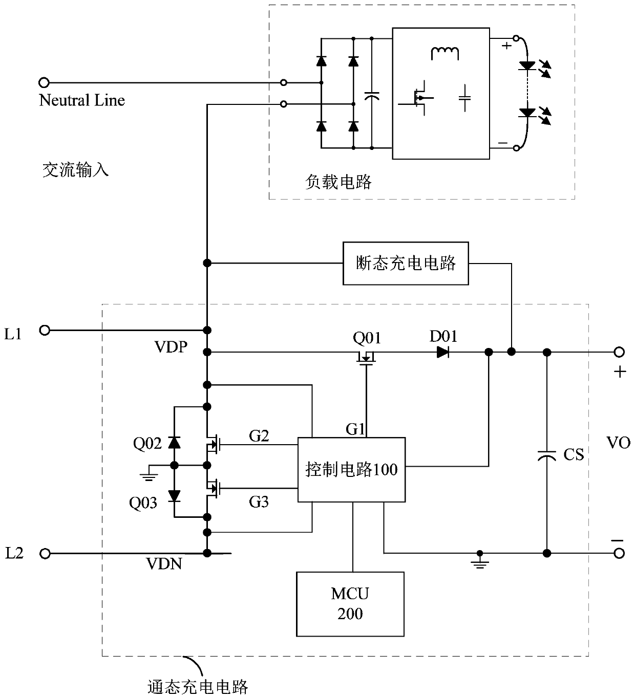
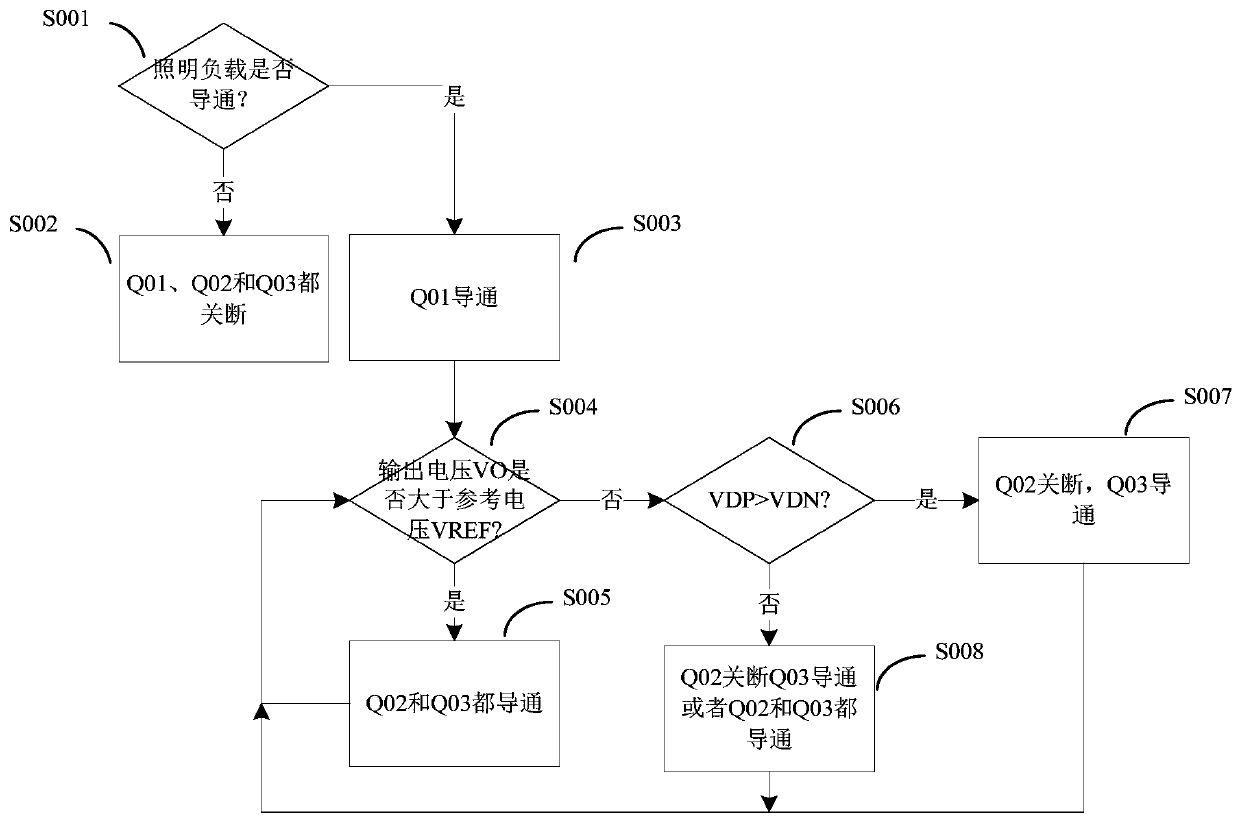
The invention discloses a control method and a control circuit of an on-state charging circuit, and the on-state charging circuit. The on-state charging circuit comprises a first switch tube, a firstconduction element, a second switch tube and a third switch tube; a first input end is connected to the output end of the on-state charging circuit through a series circuit formed by the first conduction element and the first switch tube; the first input end is connected to a reference ground through the second switch tube; a second input end is connected to the reference ground through the thirdswitch tube; when a load circuit is switched on, the first switch tube is switched on; when a voltage of the output end of the charging circuit relative to the reference ground is lower than a first voltage threshold value, the output end of the charging circuit is in a charging state; when the voltage of the output end is increased to a second voltage threshold value, the output end of the charging circuit is in a non-charging state; when the voltage of the output end of the charging circuit is reduced to the first voltage threshold value, the output end of the charging circuit is in the charging state; and in the non-charging state, the second switch tube and the third switch tube are switched on.

Description

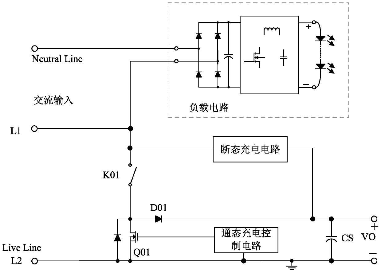
technical field [0001] The invention relates to the technical field of power electronics, in particular to a method for controlling an on-state charging circuit, a control circuit and an on-state charging circuit. Background technique [0002] The home appliance control switch panel will integrate various sensor devices to provide detection and control input interfaces for various devices or lighting fixtures. These sensor devices need to supply power to them, while there is only one live wire inside the traditional wall mechanical switch box. The wall switch power supply of the loop has become a bottleneck restricting the intelligent upgrade of traditional equipment. How to provide a stable and safe single live wire power supply solution has become a key technical difficulty. [0003] Please refer to figure 1 As shown, it is a single live wire power supply scheme. The switch K01 is a switch on the switch panel. The switch panel controls the on and off of the load circuit ...

Claims


Application Information

Patent Timeline
Patent Type & Authority Applications(China)
IPC IPC(8): H02J7/02H02J7/00
CPCH02J7/02H02J7/00Y02E60/10
Inventor 龙昊周逊伟
Owner JOULWATT TECH INC LTD
Learn More