
Combined switch device

A switching device and combination switch technology, applied in the direction of electrical switches, electrical components, circuits, etc., can solve the problems of multi-mode multi-state program control and intelligent control of controller products that cannot be realized

Active Publication Date: 2019-03-29
WUHAN AVIATION INSTR
View PDF3 Cites 0 Cited by
  • Summary
  • Abstract
  • Description
  • Claims
  • Application Information

AI Technical Summary

Problems solved by technology

[0003] The purpose of the present invention is to propose a combined switching device to solve the technical problem that many single-mode controllers cannot realize multi-mode, multi-state program control and intelligent control of controller products.

Method used


Image

  • Combined switch device
  • Combined switch device
  • Combined switch device

Examples


Embodiment Construction

[0018] Below in conjunction with accompanying drawing and embodiment the present invention will be further described:

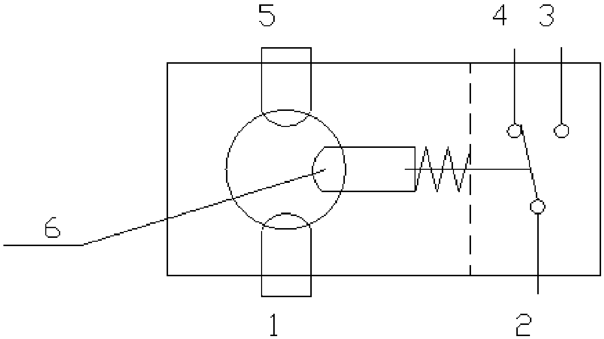
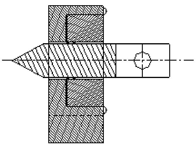
[0019] Combined switch device of the present invention, it comprises a combined switch schematic diagram such as figure 1 Shown and a schematic diagram of a metal pin as figure 2 shown. The combination switch further comprises two copper metal sheet first contacts 1 and second contacts 5, a reset piston 6 and a single-pole double-position switch. The single-pole double-set switch includes a single-pole shrapnel 2, a normally open contact 3 and a normally closed contact 4. The metal pin is a densely wound structure of conductive metal springs.

[0020] The combined switching device can be used in the starting circuit of the electric program control equipment. It works as follows:

[0021] Such as image 3 As shown, when the metal pin is inserted into the socket of the combined switch, the first contact 1 and the second contact 5 of the two copper metal ...


PUM


Abstract

The invention belongs to the technical field of electrical control, and relates to a combined switching device. The device comprises a first contact (1), a second contact (5), a reset piston (6) and asingle-pole double-throw switch. The combination switch is provided with a slotted hole matched with a metal bolt. The first contact (1), the second contact (5) and the reset piston (6) are distributed at the periphery of the slotted hole. When the metal bolt is inserted into a jack of the combination switch, the first contact (1) and the second contact (5) are conducted, the reset piston (6) moves rightwards, and the normally open end of the single-pole double-throw switch is conducted. When the metal bolt is pulled out of the combined switch base hole, the first contact (1) and the second contact (5) are disconnected, the reset piston (6) moves leftwards, and the normally closed end of the single-pole double-throw switch is conducted. According to the scheme, the technical problems thatmulti-mode and multi-state program control and intelligent control of controller products cannot be achieved in many single-mode controllers in the prior art are solved, and product upgrading is achieved.

Description

technical field [0001] The invention belongs to the technical field of electrical control, and in particular relates to a combined switch device. Background technique [0002] The combined switch device of the present invention is a key component for upgrading mechanical controller products to electromechanical controller products. Since the mechanical controller is generally controlled by a single mode, the application of the combined switching device of the present invention can upgrade the mechanical controller to an electromechanical controller, creating conditions for realizing multi-mode multi-state program control and intelligent control. The traditional plug-in switch is simple, and can only complete the circuit connection when the plug is inserted and the circuit disconnection when the plug is pulled out, and cannot solve the reverse operation, that is, the circuit is disconnected when the plug is inserted and the circuit is connected when the plug is pulled out. T...

Claims


Application Information

Patent Timeline
Patent Type & Authority Applications(China)
IPC IPC(8): H01H27/00
CPCH01H27/00
Inventor 施文斌刘亚利唐将周伟云
Owner WUHAN AVIATION INSTR
Learn More