Fragment integrated bonding device and method
A bonding method and fragmentation technology, which can be applied to attack equipment, warheads, projectiles, etc., can solve the problems that bonding equipment cannot achieve integrated bonding and the bonding method is inefficient, and achieve a simple structure and improve bonding efficiency. , the effect of low cost
- Summary
- Abstract
- Description
- Claims
- Application Information
AI Technical Summary
Problems solved by technology
Method used
Image
Examples
Embodiment 1
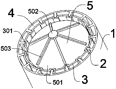
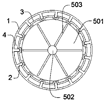
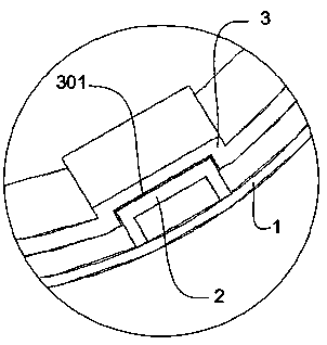
[0044] refer to figure 1 , figure 2 , image 3As shown, one embodiment of the present invention is an integrated bonding device for fragments, the device includes a support sleeve 1, a vertical isolation plate 2, and an isolation sleeve 3; the above support sleeve 1 is used to wrap the shell; the support sleeve 1 and the shell The gap between the bodies A forms an available space for arranging the fragments by the vertical isolation plate 2; the above-mentioned vertical isolation plate 2 is installed on the inner wall of the support sleeve 1; the above-mentioned isolation sleeve 3 is provided with a groove 301, and the above-mentioned groove 301 Matching with the vertical isolation plate 2, it is used to separate the fragments from the isolation sleeve 3 to prevent the fragments from directly contacting the shell. Partition the fragments to prevent the fragments from directly contacting the shell; and there is also a certain gap between the spacer 3 and the outer wall of th...
Embodiment 2
[0049] Based on the above examples, refer to Figure 4 , Figure 5 , Figure 6 As shown, another embodiment of the present invention is,
[0050] The above-mentioned device also includes a diverter plate 5, the above-mentioned diverter plate 5 includes a partition plate 501, a rotating disc 502, and a strip plate 503, and the above-mentioned split disc 501 is used to install the housing on the top, and the above-mentioned rotating disc 502 is installed on the upper end of the split disc 501. The strip plate 503 is installed on the rotating disk 502, and is used to drive the strip plate 503 to rotate and contact the fragments by the rotating disk 502; wherein the diverter plate 5 is located on the shell A, and is fixedly connected to the upper end of the shell A by the dividing plate 501 to divide The disk 501 is connected with the housing A by a key; its rotating disk 502 is placed on the upper end of the dividing disk 501, and its dividing disk 501 is fixedly connected with...
Embodiment 3
[0055] Based on the above examples, refer to Figure 7 , Figure 8 , Figure 9 As shown, another embodiment of the present invention is that, in order to quickly arrange the fragments in the vertical direction, the above-mentioned vertical separation plate 2 is in a convex shape, and the above-mentioned vertical separation plate 2 is two or more, and adjacent The gap between the two vertical isolation plates 2 is the same, and the gap is greater than or equal to the width of the fragment. The above-mentioned isolation sleeve 3, support sleeve 1 and vertical isolation plate 2 form an arrangement track 4, which is used to fill the fragments by the arrangement track 4. The vertical isolation plate 2 is evenly distributed on the support sleeve 1, the outer wall of the isolation sleeve 3, the inner wall of the support sleeve 1 and the side wall of the vertical isolation plate 2 form an arrangement track 4, and the fragments are placed in the arrangement track 4 by putting fragment...
PUM
 Abstract
Description
Claims
Application Information
 - R&D
- Intellectual Property
- Life Sciences
- Materials
- Tech Scout
- Unparalleled Data Quality
- Higher Quality Content
- 60% Fewer Hallucinations
Browse by: Latest US Patents, China's latest patents, Technical Efficacy Thesaurus, Application Domain, Technology Topic, Popular Technical Reports.
© 2025 PatSnap. All rights reserved.Legal|Privacy policy|Modern Slavery Act Transparency Statement|Sitemap|About US| Contact US: help@patsnap.com


