
Power transmission line fault monitoring device and method

A transmission line and fault monitoring technology, which is applied in the direction of fault location and fault detection according to the conductor type, can solve the problems that operators are difficult to make, the monitoring range is limited, and the specific information of equipment cannot be provided in time, so as to solve the problem of icing along the line difficult problems, comprehensive monitoring information, and the effect of saving manpower and material resources

Inactive Publication Date: 2019-08-02
STATE GRID SHANDONG ELECTRIC POWER +1
View PDF7 Cites 9 Cited by
  • Summary
  • Abstract
  • Description
  • Claims
  • Application Information

AI Technical Summary

Problems solved by technology

The monitoring scope of the existing SCADA (Supervisory Control And Data Acquisition, that is, data acquisition and monitoring control) system is limited to the main parameters of the system, and the specific information of each important equipment that constitutes the system cannot be provided in time, making it difficult for operators to make decisions in the face of accidents. correct handling

Method used


Image

  • Power transmission line fault monitoring device and method
  • Power transmission line fault monitoring device and method
  • Power transmission line fault monitoring device and method

Examples


Embodiment Construction

[0043]The present disclosure will be further described below in conjunction with the accompanying drawings and embodiments.

[0044] It should be noted that the following detailed description is exemplary and intended to provide further explanation of the present disclosure. Unless defined otherwise, all technical and scientific terms used in this disclosure have the same meaning as commonly understood by one of ordinary skill in the art to which this disclosure belongs.

[0045] It should be noted that the terminology used here is only for describing specific implementations, and is not intended to limit the exemplary implementations according to the present application. As used herein, unless the context clearly dictates otherwise, the singular is intended to include the plural, and it should also be understood that when the terms "comprising" and / or "comprising" are used in this specification, they mean There are features, steps, operations, means, components and / or combin...


PUM


Abstract

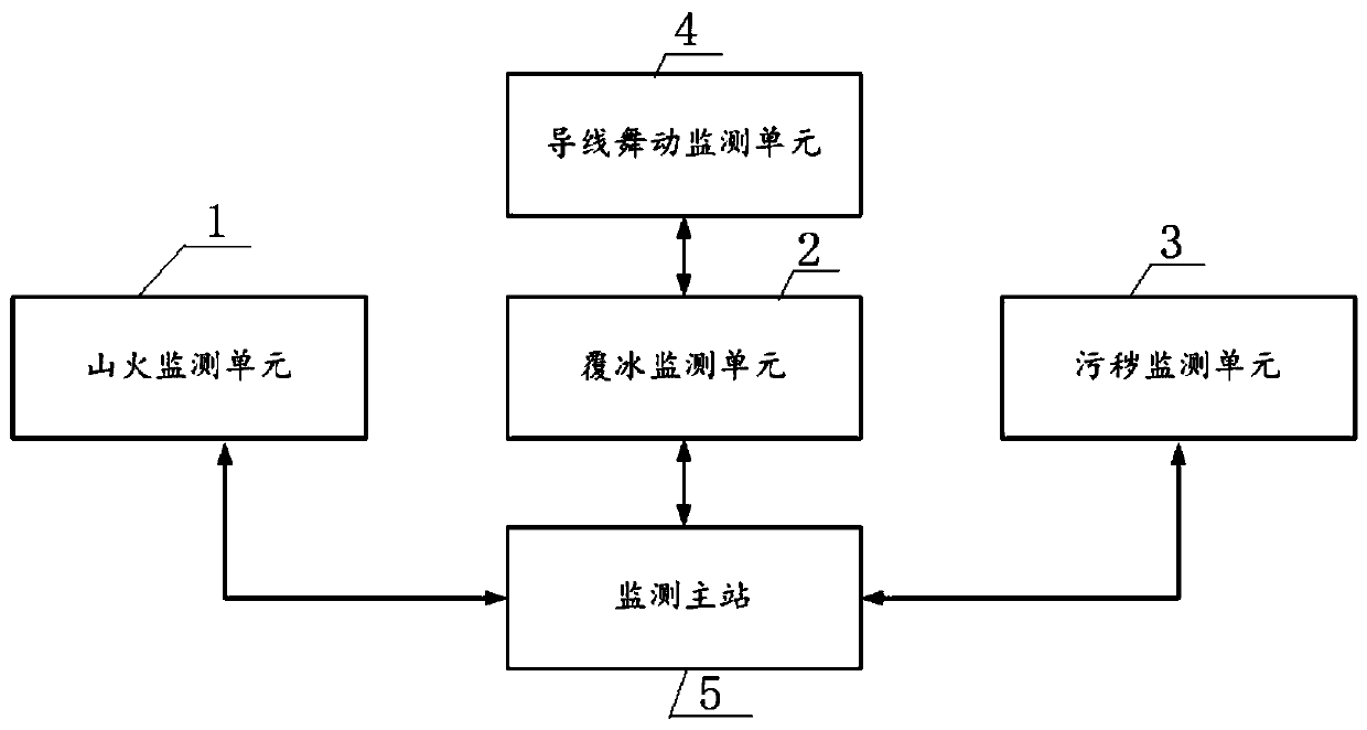
The invention discloses a power transmission line fault monitoring device and method, and can carry out comprehensive monitoring on a fault state of a power transmission line. The device comprises a mountain fire monitoring unit, an ice coating monitoring unit, a dirty monitoring unit, a conductor galloping monitoring unit and a monitoring main station, wherein the mountain fire monitoring unit isused for monitoring whether an abnormal heat source exists in a power transmission line passage and tower region, if yes, timely carrying out fire extinguishing, and uploading monitored data to the monitoring main station; the ice coating monitoring unit is used for monitoring conductor tension and meteorological environment data near the line and uploading the monitored data and data monitored by the conductor galloping monitoring unit to the monitoring main station; the dirty monitoring unit is used for detecting equivalent salt deposit density data of an insulator of the power transmissionline and uploading the monitored data to the monitoring main station; the conductor galloping monitoring unit is used for monitoring galloping information of the line and transmitting the galloping information to the ice coating monitoring unit; and the monitoring main station is used for receiving the data monitored by the mountain fire monitoring unit, the ice coating monitoring unit, the dirtymonitoring unit and the conductor galloping monitoring unit and carrying out analysis on a condition of the power transmission line

Description

technical field [0001] The present disclosure relates to the field of transmission line status monitoring, in particular to a transmission line fault monitoring device and method. Background technique [0002] The transmission line crosses mountains, rivers, etc., and is far away from the office of the operation and maintenance personnel. The time from the office to the transmission line is closely related to the area under the jurisdiction of the operation and maintenance department, topography, road conditions, etc. The status monitoring data of the transmission and transformation line It is a large part of the data in the smart grid, including not only the online status monitoring data, but also the basic information of the equipment, experimental data, defect records, etc., and the requirements for the reliability and real-time performance of data processing are very high. How to quickly locate the fault after the fault of the transmission line is an important technical ...

Claims


Application Information

Patent Timeline
IPC IPC(8): G01R31/08
CPCG01R31/085
Inventor 吕文齐艳王东阳丁玲耿敏姜玲
Owner STATE GRID SHANDONG ELECTRIC POWER
Learn More