
Electronic device and method for switching camera modules

A technology of electronic devices and camera modules, which is applied in the direction of electrical digital data processing, input/output process of data processing, instruments, etc., can solve the problems of unsightly appearance, inability to be easily disassembled or installed, etc., so as to reduce process procedures and save manufacturing costs , Solve the effect of hacking and peeping

Active Publication Date: 2019-08-02
ACER INC
View PDF6 Cites 2 Cited by
  • Summary
  • Abstract
  • Description
  • Claims
  • Application Information

AI Technical Summary

Problems solved by technology

However, this method has the problem of being unsightly and not being able to be easily disassembled or installed

Method used


Image

  • Electronic device and method for switching camera modules
  • Electronic device and method for switching camera modules
  • Electronic device and method for switching camera modules

Examples


Embodiment Construction

[0062] In order to make the purpose, features, and advantages of the present disclosure more comprehensible, the following specific embodiments are described in detail with accompanying drawings. Wherein, the configuration of each element in the embodiment is for the purpose of illustration, and is not intended to limit the present disclosure. In addition, part of the reference numerals in the embodiments are repeated for the purpose of simplifying the description, and do not imply the correlation between different embodiments. The directional terms mentioned in the following embodiments, such as: up, down, left, right, front or back, etc., are only directions referring to the attached drawings. Accordingly, the directional terms used are for illustration and not for limitation of the present disclosure.

[0063]It must be understood that elements not specifically described or illustrated may exist in various forms well known to those skilled in the art. In addition, when a ...


PUM


Abstract

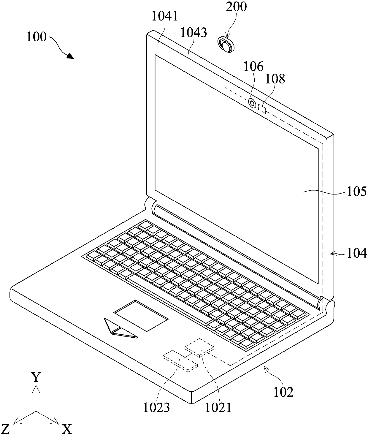
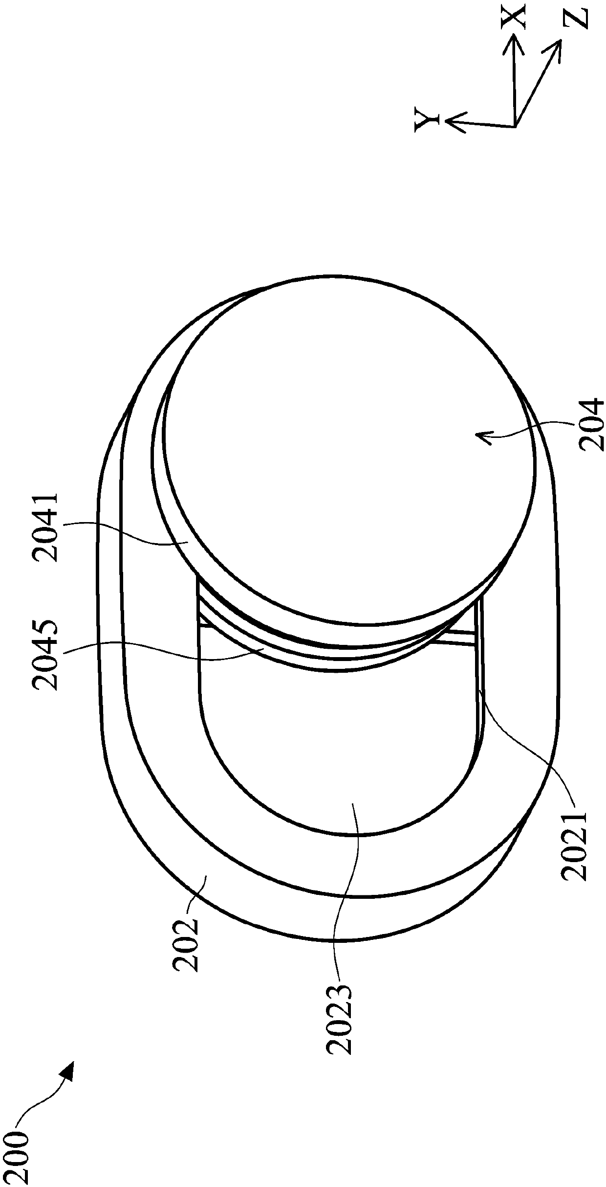
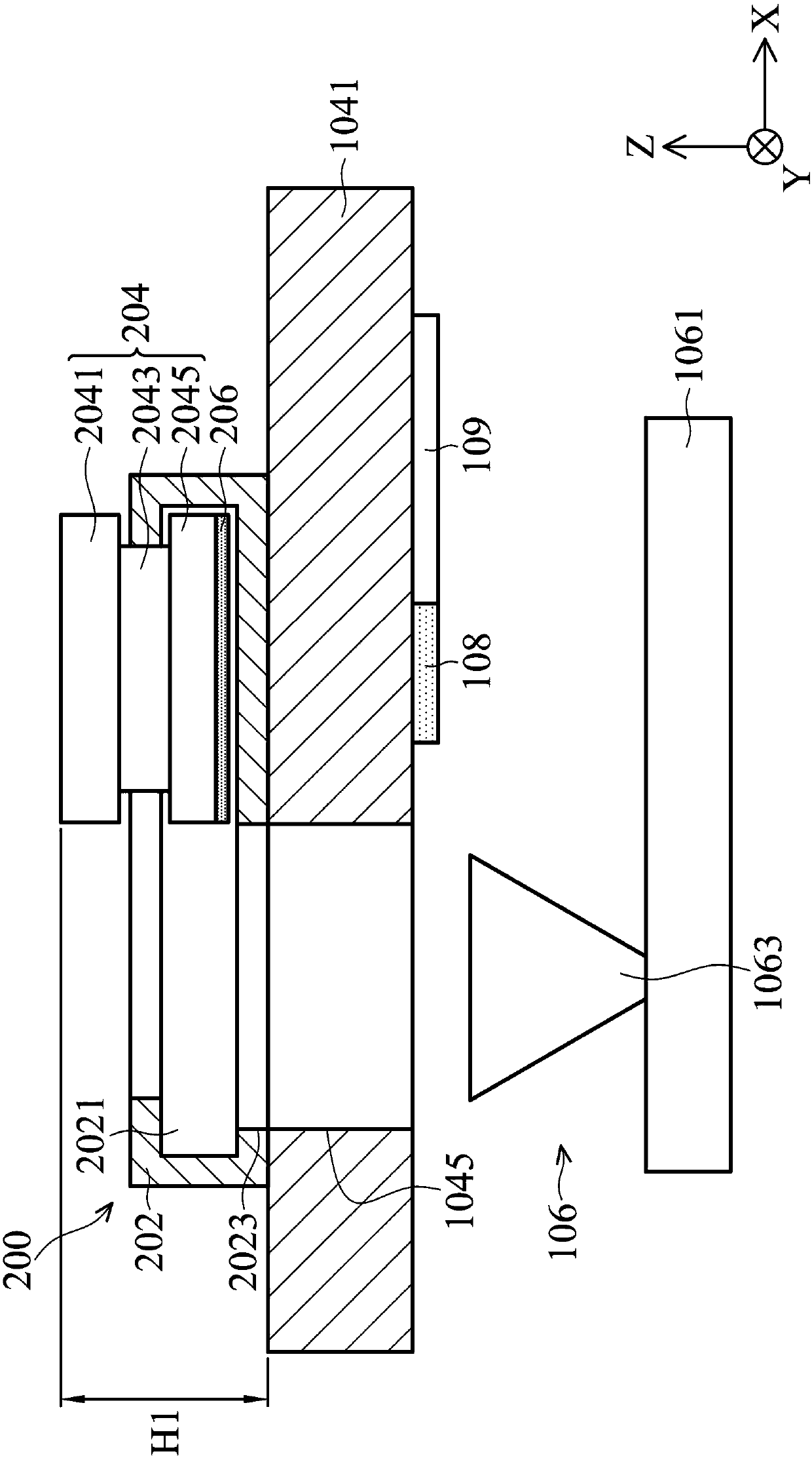
The invention relates to an electronic device and a method for switching camera modules. The electronic device comprises a camera module, a first capacitive sensing element, a monitoring circuit and ashielding module. The monitoring circuit is electrically connected to the first capacitive sensing element and the camera module. The shielding module comprises a moving part and a first conductive element. The moving part moves relative to the camera module. The first conductive element is disposed on the moving member. When the moving part is positioned at a first position, the first capacitivesensing element senses the first conductive element to generate a sensing signal, the monitoring circuit activates the camera module according to the sensing signal, and the monitoring circuit turnsoff the camera module when the moving member is located at a second position and the first capacitive sensing element does not sense the first conductive element.

Description

technical field [0001] The invention relates to an electronic device, in particular to an electronic device that uses a shielding module to cover a camera module. Background technique [0002] With the development of technology, many electronic devices, such as smart phones or notebook computers, have the function of taking photos or recording videos. Through the camera module installed on the electronic device, the user can operate the electronic device to obtain various photos. [0003] However, today's society pays more and more attention to personal privacy, and the camera module on the electronic device may have the risk of exposing personal privacy. For example, there may be hackers invading the user's electronic device through illegal or informal means, and spying or secretly recording the daily behavior of the user without the user's knowledge. Therefore, many users will physically block the lens of the camera module by using patches, black tape, or blocking object...

Claims


Application Information

Patent Timeline
Patent Type & Authority Applications(China)
IPC IPC(8): G06F1/16G06F1/3287G06F3/044G06F11/30G06F11/32
CPCG06F1/1675G06F1/3287G06F3/044G06F11/3058G06F11/324
Inventor 柯杰斌
Owner ACER INC
Learn More