

Multifunctional milling head mounting device for electrolyzing-electric spark milling
A mounting device and multi-functional technology, which is applied in the field of multi-functional milling head mounting device for electrolytic EDM, can solve the problems of poor installation and use flexibility, insufficient liquid supply in the processing area, and poor processing stability, etc., and achieves a compact structure , good chip removal and cooling function, and the effect of overall device stability
- Summary
- Abstract
- Description
- Claims
- Application Information
AI Technical Summary
Problems solved by technology
Method used
Image

Examples
Embodiment 1
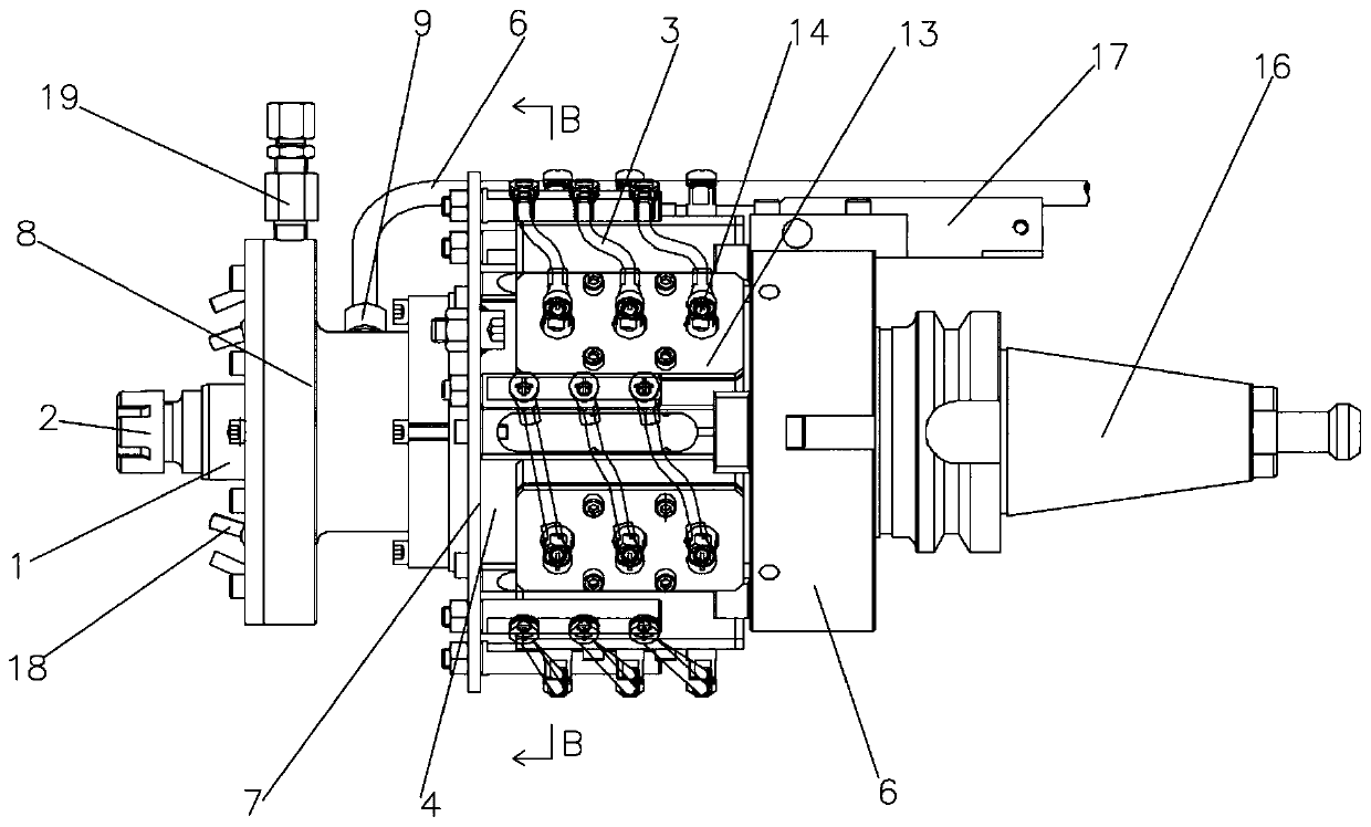
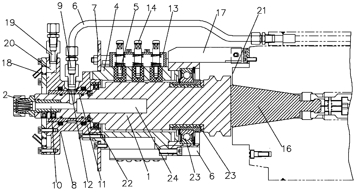
[0033] Such as Figure 1 to Figure 3 As shown, the present embodiment provides a multifunctional milling head installation device for electrolytic spark milling, including a conductive shaft 1, the right end of the conductive shaft 1 is provided with a joint assembly connected to the driving mechanism on the basic processing platform, and the conductive shaft The left end of 1 is equipped with a ferrule 2 for fixing the milling head. The ferrule 2 can be selected in different specifications, and can be clamped and replaced with different specifications of the electrode milling head, and can also realize the quick replacement of the ordinary milling head and the electrode milling head. In the embodiment, the ferrule 2 is preferably an ER32 ferrule; the conductive shaft 1 is provided with an installation sleeve 8 and a brush holder 4 in sequence from left to right, and the installation sleeve 8 and the brush holder 4 are fixedly connected, and the installation sleeve 8 is connect...
Embodiment 2
[0040] combine figure 2 and image 3 As shown, the present embodiment is further optimized on the basis of embodiment 1, specifically:
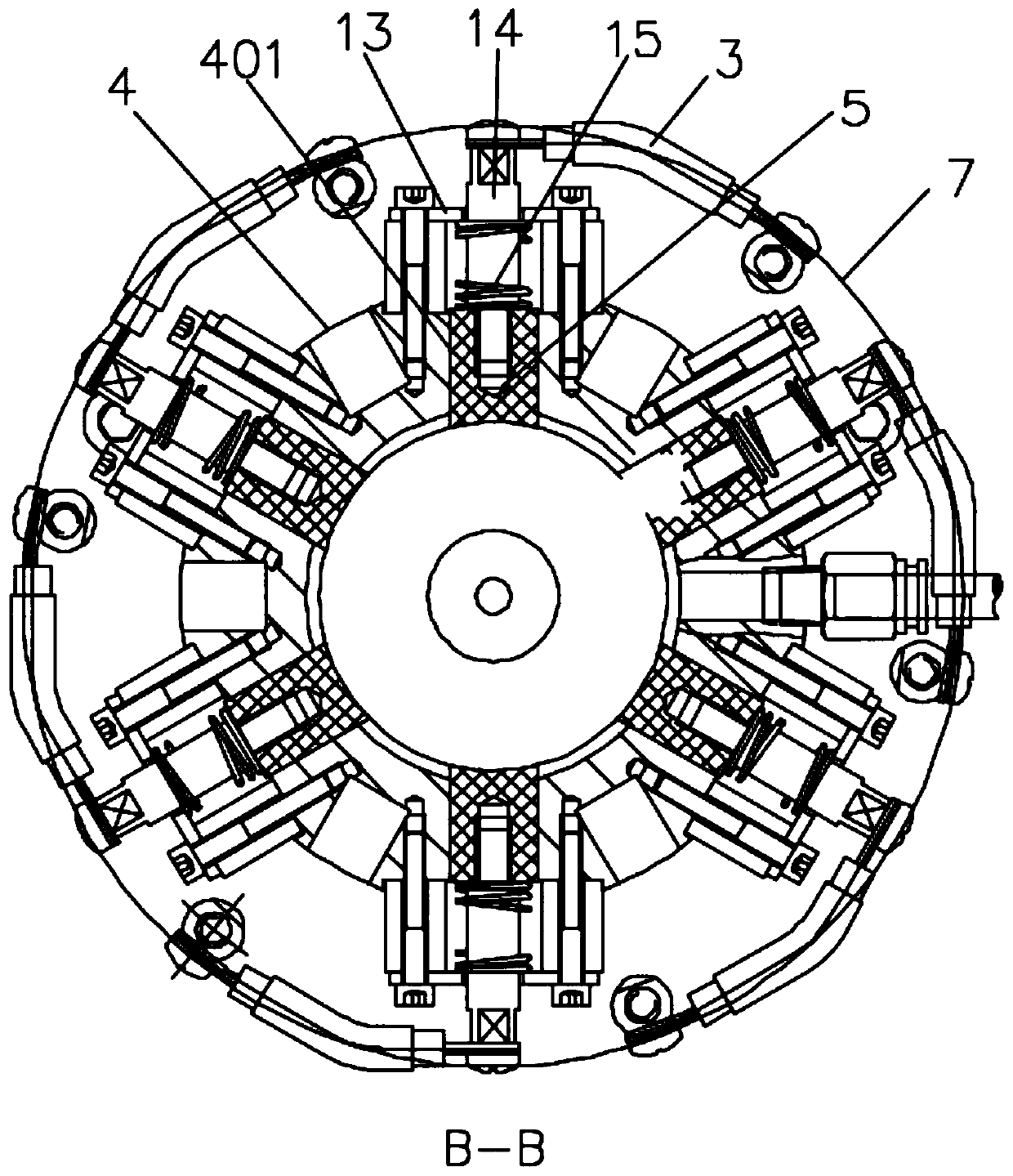
[0041] There are three groups of 18 through-holes 401 evenly penetrating through the brush holder 4, and each group has 6 holes. The center lines are in the same plane and are perpendicular to the axis line of the conductive shaft 1, and each group of through holes 401 is distributed at an equal angle with the intersection point as the center of the circle. The brush 5 in contact with the shaft 1, one brush 5 in each through hole 401, the brush 5 is a graphite brush, the brush holder 4 is fixedly connected with a backing plate 13 directly above the through hole 401, and the backing plate 13 A conductive column 14 that can slide on the backing plate 13 is vertically pierced on the top. One end of the conductive column 14 facing the through hole 401 extends into the through hole 401 and is fixedly connected with the brush 5. The end of the c...
PUM
 Abstract
Description
Claims
Application Information