Convenience apparatus for vehicle

A sliding, foot rest technology, applied in special positions of vehicles, vehicle parts, vehicle seats, etc., can solve the problem that traditional foot rests are not suitable for use in autonomous vehicles

Active Publication Date: 2019-08-06
HYUNDAI MOTOR CO LTD +2
View PDF12 Cites 3 Cited by
  • Summary
  • Abstract
  • Description
  • Claims
  • Application Information

AI Technical Summary

Problems solved by technology

However, in terms of maximizing the use of space, such traditional footrests are not suitable for use in autonomous vehicles

Method used


Image

  • Convenience apparatus for vehicle
  • Convenience apparatus for vehicle
  • Convenience apparatus for vehicle

Examples


Embodiment Construction

[0024] Reference will now be made in detail to the exemplary embodiments of the present application, examples of which are illustrated in the accompanying drawings. Wherever possible, the same reference numbers will be used throughout the drawings to refer to the same or like parts.

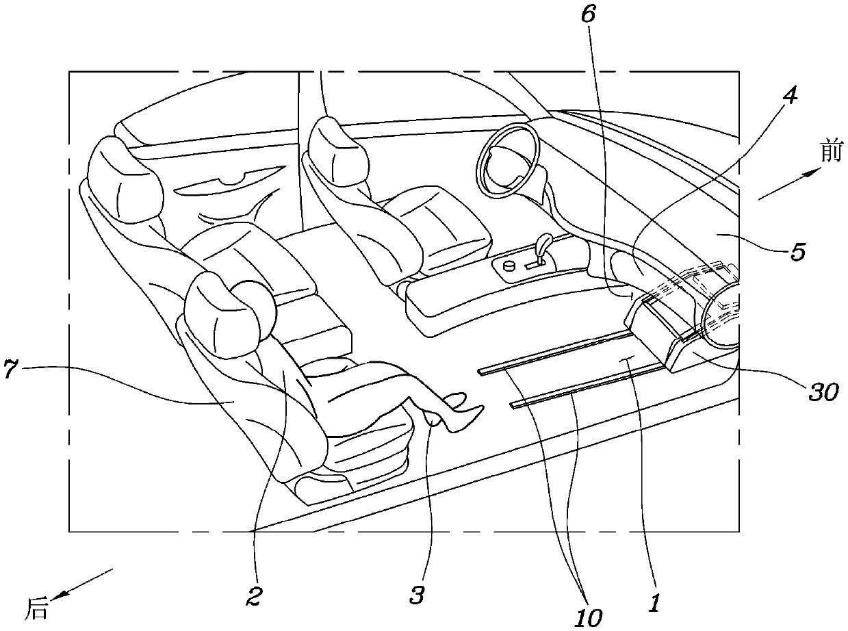
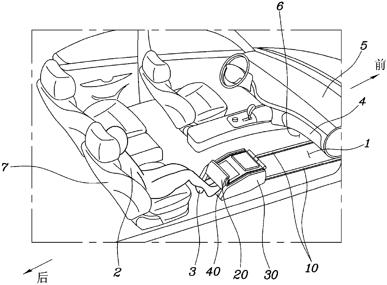
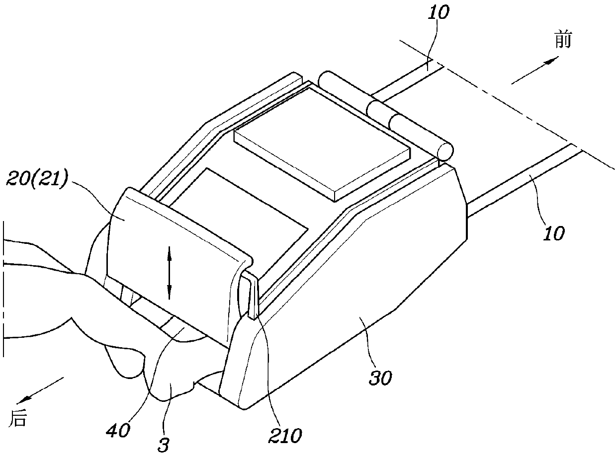
[0025] Such as Figure 1 to Figure 8 As shown, the sliding footrest device for vehicles according to the present application includes: a guide rail 10, a footrest housing 30 and a footrest box 40, and the guide rail 10 is installed on the floor 1 arranged beside the driver's seat , to extend in the forward and backward directions; the footrest housing 30 is engaged with the guide rail 10 so as to slide along the guide rail 10 in the forward and rearward direction, and is provided with a door configured to be able to be opened or closed 20 ; the footrest box 40 is arranged in the footrest housing 30 and is configured to allow the passenger 2 in the rear seat 7 to place the feet 3 in the footrest ...


PUM


Abstract

The invention discloses a sliding-type footrest device for a vehicle, and the device includes a guide rail mounted on a floor panel and extending in a forward-and-backward direction; a footrest housing engaged with the guide rail to slide along the guide rail in the forward-and-backward direction, the footrest housing having a door configured to be opened or closed; and a footrest box disposed inside the footrest housing and allowing a backseat passenger to place feet into the footrest while the door is open.

Description

technical field [0001] The present application relates to a sliding type foot rest apparatus for a vehicle, in which a rear seat passenger can place their feet, and which can perform a heating function, a ventilation function and a massage function. Background technique [0002] A self-driving vehicle is an intelligent vehicle that travels autonomously, specifically, it can travel to a set destination autonomously by itself without requiring a driver to operate a steering wheel, an accelerator pedal, a brake pedal, and the like. Currently, the development of such self-driving vehicles is being accelerated. [0003] When such self-driving vehicles become commercially available, passengers may want to rest in as much comfort as possible. For example, a rear seat passenger may want to take a break to stretch his / her legs. [0004] A conventional foot rest for vehicles is formed as a plate-like configuration that supports only the passenger's feet when the rear seat passenger ...

Claims


Application Information

Patent Timeline
Patent Type & Authority Applications(China)
IPC IPC(8): B60N3/06
CPCB60N3/063B60N99/00B60N3/06B60N2/56B60N2/976B60R7/04G05G1/60
Inventor 金殷秀郑大瀷金在学张承赫裵秉完郑圣频姜信正卞得圭
Owner HYUNDAI MOTOR CO LTD
Why Eureka
Try Eureka