A fabric wear resistance detection system and detection method

A detection system and wear resistance technology, applied in the direction of testing wear resistance, measuring devices, analyzing materials, etc., can solve problems such as testing fabric wear resistance

Active Publication Date: 2021-10-08
阜阳市豹子头服饰科技有限公司
View PDF8 Cites 0 Cited by
  • Summary
  • Abstract
  • Description
  • Claims
  • Application Information

AI Technical Summary

Problems solved by technology

But the invention can't test the abrasion resistance of fabrics under many conditions

Method used


Image

  • A fabric wear resistance detection system and detection method
  • A fabric wear resistance detection system and detection method
  • A fabric wear resistance detection system and detection method

Examples


specific Embodiment approach 1

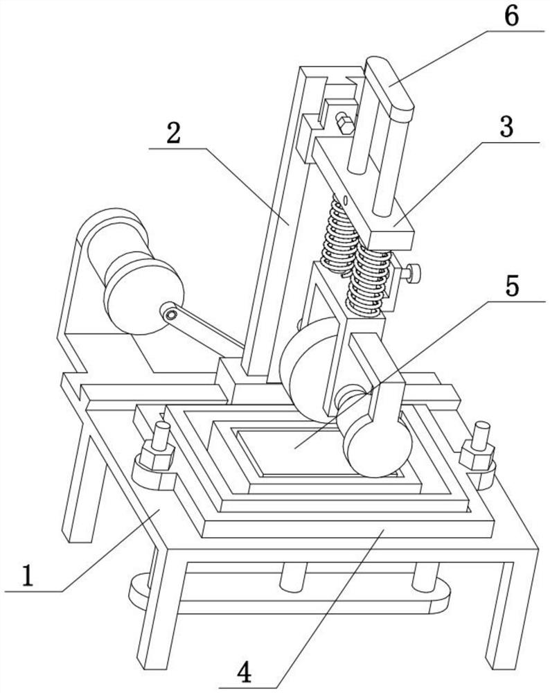
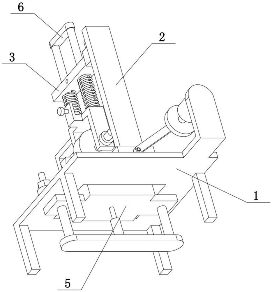
[0038] Combine below Figure 1-10 This embodiment is described. The present invention relates to the field of fabric detection, more specifically, a fabric wear resistance detection system and detection method, including a chassis 1, a vertical seat 2, a horizontal seat 3, a rectangular fixed frame 4, and a bottom pad 5 And friction mechanism 6, the present invention can test the abrasion resistance of fabric under various conditions.

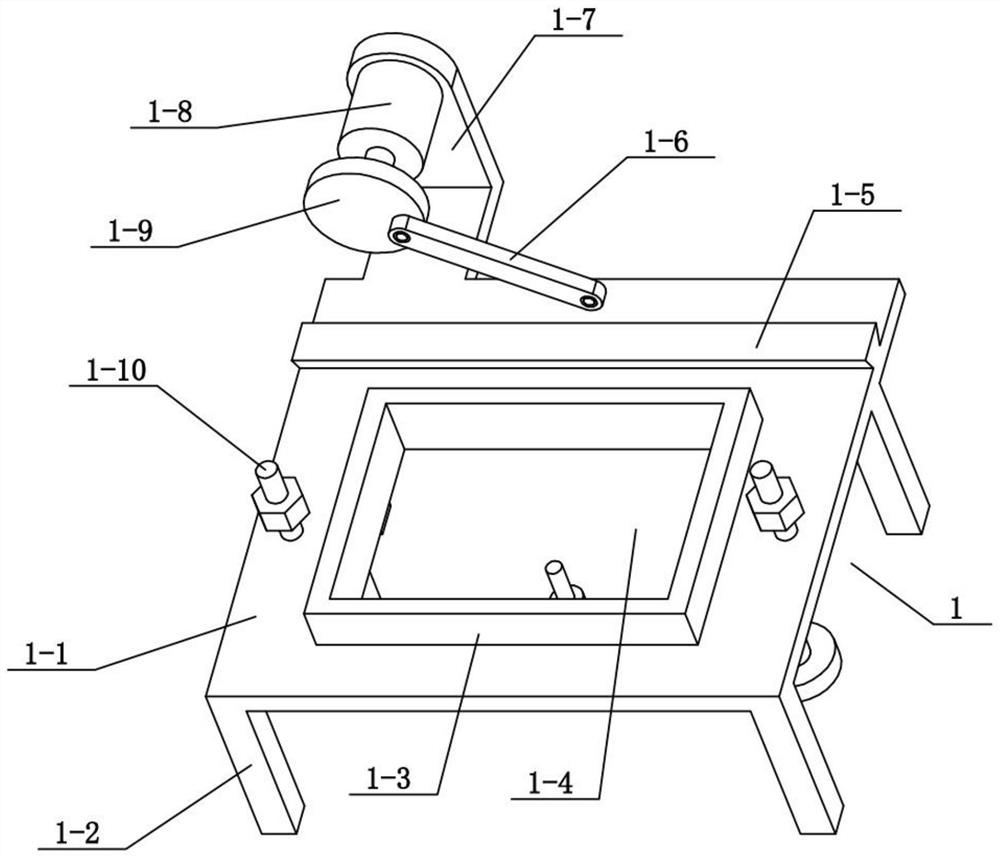
[0039] The chassis 1 includes a flat plate 1-1, a support column 1-2, a rectangular convex edge 1-3, a rectangular hole 1-4 and a threaded stub 1-10, and the four corners of the lower end of the flat plate 1-1 are fixedly connected There are support columns 1-2, and the flat plate 1-1 is provided with a rectangular hole 1-4, and the outer periphery of the rectangular hole 1-4 on the flat plate 1-1 is fixedly connected with a rectangular convex edge 1-3, and the left and right sides of the flat plate 1-1 Both ends are fixedly connected with thr...

specific Embodiment approach 2

[0043] Combine below Figure 1-10 To illustrate this embodiment, the underframe 1 also includes a trapezoidal slide rail I1-5, an inclined connecting rod 1-6, a motor frame I1-7, a motor I1-8 and a turntable 1-9, and the upper end of the flat plate 1-1 is fixedly connected There is a trapezoidal slide rail I1-5, a motor frame I1-7 is fixedly connected to the flat plate 1-1, a motor I1-8 is fixedly connected to the motor frame I1-7, and a turntable 1-8 is fixedly connected to the output shaft of the motor I1-8. 9. One end of the oblique connecting rod 1-6 is hingedly connected to the eccentric position of the turntable 1-9.

specific Embodiment approach 3

[0044] Combine below Figure 1-10 To illustrate this embodiment, the underframe 1 also includes a horizontal bottom plate 1-11, a cylindrical vertical rod 1-12 and an electric telescopic rod 1-13, and the left and right ends of the lower end of the flat plate 1-1 are fixedly connected with a cylindrical vertical rod 1-13. 12. A horizontal bottom plate 1-11 is fixedly connected between the lower ends of the two cylindrical vertical rods 1-12, and an electric telescopic rod 1-13 is fixedly connected in the middle of the upper end of the horizontal bottom plate 1-11.


PUM


Abstract

The invention relates to the field of fabric detection, more specifically a fabric wear resistance detection system and detection method, including a chassis, a vertical seat, a horizontal seat, a rectangular fixed frame, a bottom pad and a friction mechanism. The present invention can be used in various Test the abrasion resistance of the fabric under the condition. The underframe includes a flat plate, a supporting column, a rectangular convex edge, a rectangular hole and a threaded stub, the four corners of the lower end of the flat plate are fixedly connected with supporting columns, the flat plate is provided with a rectangular hole, and the outer circumference of the rectangular hole is fixed on the flat plate. It is connected with a rectangular convex edge, and the left and right ends of the plate are fixedly connected with threaded short columns, and the two threaded short columns are connected with nuts through threads, the rectangular fixed frame is inserted on the rectangular convex edge, and the left and right ends of the rectangular fixed frame are respectively The clearance fit is inserted on two threaded short columns, and the two nuts are located on the upper side of the rectangular fixed frame; the vertical seat includes a bottom slider, a vertical plate and a trapezoidal slide rail II, the bottom slider is connected to the flat plate, and the bottom slider The upper end of the block is fixedly connected with a riser, and the front side of the riser is provided with a trapezoidal slide rail II.

Description

technical field [0001] The invention relates to the field of fabric detection, in particular to a fabric wear resistance detection system and detection method. Background technique [0002] The application number is CN201711454625.5, which discloses a wear-resistant detection device for shoe materials. The invention belongs to the field of wear-resistant detection devices, especially a wear-resistant detection device for shoe materials. The friction method is single, which leads to the high cost and low detection efficiency caused by the need to use multiple devices for wear-resistant testing of shoe leather materials. The following solutions are proposed, including a wear-resistant testing device for shoe materials , including a first U-shaped mounting plate fixed on the top of the base, a dust collection box is fixed on one side of the first U-shaped mounting plate, and a group of first hydraulic cylinders arranged in parallel are fixed on the top of the first U-shaped mou...

Claims


Application Information

Patent Timeline
Patent Type & Authority Patents(China)
IPC IPC(8): G01N3/56G01N3/02
CPCG01N3/02G01N3/56
Inventor 潘一洲
Owner 阜阳市豹子头服饰科技有限公司
Why Eureka
Try Eureka