Cable wear resistance test device

A technology of wear resistance and testing device, applied in the field of lighting, can solve problems such as the inability to guarantee the safety and reliability of cables

Inactive Publication Date: 2016-12-28
SHENZHEN OCEANS KING LIGHTING ENG CO LTD +1
View PDF8 Cites 0 Cited by
  • Summary
  • Abstract
  • Description
  • Claims
  • Application Information

AI Technical Summary

Problems solved by technology

In the prior art, there is no tooling specially used for testing the wear resistance of cables, so the safety and reliability of cables in actual use cannot be guaranteed

Method used


Image

  • Cable wear resistance test device
  • Cable wear resistance test device

Examples


Embodiment Construction

[0018] The following will clearly and completely describe the technical solutions in the embodiments of the present invention with reference to the drawings in the embodiments of the present invention.

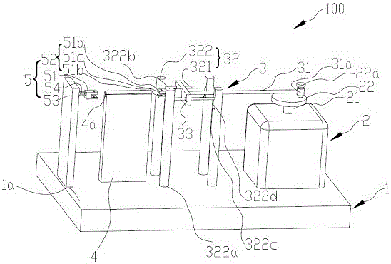
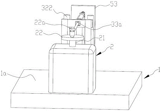
[0019] Please also refer to Figure 1 to Figure 2 , a cable wear resistance testing device 100 provided in an embodiment of the present invention is used to test the wear resistance of a tested cable (not shown). The cable wear resistance testing device 100 includes a base 1, a motor 2, a transmission part 3, an accommodating part 4 and a clamping unit 5, and the motor 2, the transmission part 3, the accommodating part 4 and the clamping unit 5 are all Set on the base 1.

[0020] The base 1 includes a bearing surface 1a. In this embodiment, the structure of the base 1 is a cuboid, and the material of the base 1 is steel. Certainly, in other embodiments, the material of the base 1 may also be iron or aluminum.

[0021] The motor 2 is arranged on the bearing surface 1a and i...


PUM


Abstract

The invention discloses a cable wear resistance testing device, which comprises a base, a motor, an accommodating part, a transmission part and a clamping unit; the motor is arranged on the bearing surface of the base, and the motor includes a rotating part; the accommodating part is fixedly arranged on the base On the bearing surface, a through hole is opened in the receiving part, and the inner side of the through hole rubs against the tested cable; one end of the transmission part is fixed on the rotating part, and reciprocates linearly along the central axis of the through hole, and is located at Between the accommodating part and the rotating motor; the clamping unit includes a first cable clamp, a second cable clamp and a fixing base, the first cable clamping is set on the other end of the transmission part; the fixing base is set on the bearing surface of the base, and the second The two cable clamps are connected to the fixing seat through springs. The cable wear resistance test device makes the tested cable reciprocate linearly with the transmission part, and makes the tested cable rub against the through hole used to place the tested cable, so as to test the tested cable. abrasion resistance.

Description

technical field [0001] The invention relates to the field of lighting, in particular to a device for testing the wear resistance of cables. Background technique [0002] Special lamps are widely used in various industries, and the requirements for the reliability and safety of special lamps are getting higher and higher. When the lamps are installed on ships, the cables will be installed in the pipes. [0003] When the ship is sailing at sea, the sea wind and the impact of the ocean will cause the cable to rub back and forth in the pipeline, making the cable protective layer thinner, and the position where the cable protective layer is worn may be exposed to instantaneous high voltage of several thousand volts. being broken down, causing the cable to be a potential safety hazard during actual use. Therefore, when designing lamps, the wear resistance of the cables must be investigated. In the prior art, there is no tooling specially used for testing the wear resistance of ...

Claims


Application Information

Patent Timeline
Patent Type & Authority Patents(China)
IPC IPC(8): G01N3/56
Inventor 周明杰汪辉
Owner SHENZHEN OCEANS KING LIGHTING ENG CO LTD
Why Eureka
Try Eureka