Wire and cable wear resistance detection device

A technology of wear resistance and detection device, which is applied in the field of wire and cable, can solve the problems of wear resistance detection dependence, wear, and wire and cable are susceptible to friction, and achieve the effect of increasing friction and increasing friction

Pending Publication Date: 2022-02-11
安徽扬子线缆有限公司
View PDF0 Cites 4 Cited by
  • Summary
  • Abstract
  • Description
  • Claims
  • Application Information

AI Technical Summary

Problems solved by technology

[0003] Since the wires and cables are very susceptible to friction during use, resulting in wear and tear, the wires and cables in the insulating outer sheath are exposed to the external environment. In order to reduce the occurrence of similar situations, after the insulating outer sheath is produced, it needs to be extracted from it. Partially detect the wear resistance of the cable. The existing detection device relies on manual friction inspection for the wear resistance detection of the cable, and cannot perform continuous and repeated friction operations. A wear resistance detection device for wires and cables is proposed.

Method used


Image

  • Wire and cable wear resistance detection device
  • Wire and cable wear resistance detection device
  • Wire and cable wear resistance detection device

Examples


Embodiment 1

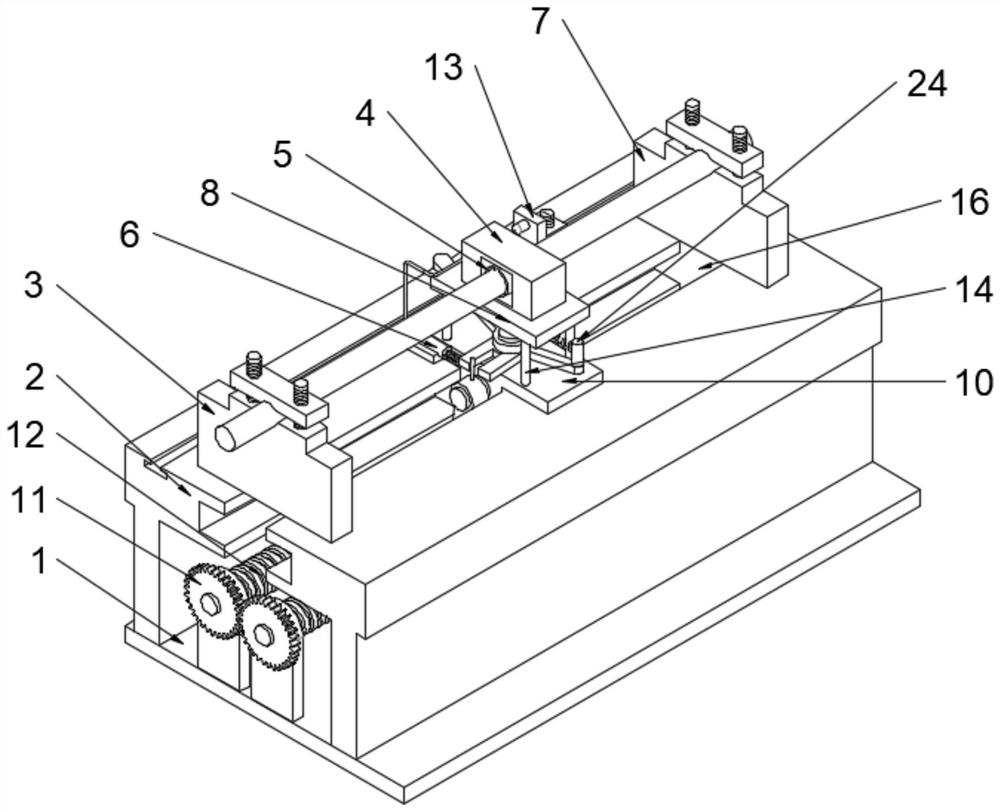
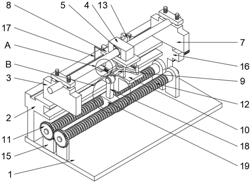
[0028] see Figure 1 to Figure 8 , the present invention provides a technical solution: a wear resistance detection device for wires and cables, two support frames 2 are symmetrically arranged on the upper surface of the mounting seat 1, and a limiting groove is opened on the opposite side of the support frame 2 and passes through the limit The groove is slidably connected with a sliding block 10, and the sliding block 10 is provided with a friction mechanism for repeatedly testing the wear resistance of the cable. The friction mechanism includes four support columns 14 fixed on the upper surface edge of the sliding block 10, four The upper surface of the support column 14 is fixedly connected with a support plate 8, and a detection block 4 is fixedly installed on the support plate 8. The surface of the detection block 4 is provided with a mounting groove, and the inner wall of the mounting groove is symmetrically provided with two contact pieces 5 that are in contact with the ...

Embodiment 2

[0040] Such as Figure 4 and Figure 5 As shown, on the basis of Embodiment 1, it is basically the same as Embodiment 1. Furthermore, the surface of the sliding block 16 is provided with a threaded hole and is screwed with a screw 28 through the threaded hole, and the screw 2 28 runs through the sliding block. The threaded hole on the second 16 is fixedly connected with the connecting shaft of the screw rod one 12.

[0041] When the screw rod two 28 rotates, the sliding block two 16 can be opened in the limit groove on the opposite side of the support frame 2 to carry out limit sliding, and the thread on the sliding block two 16 is closer to that on the screw rod one 12. When rotating, the sliding block 2 16 can be moved in a small distance, and the clamp 2 7 can move slowly with a small distance along with the screw rod 2 28, so that the clamp 2 7 can slowly pull the cable to move, and the cable can be slowly pulled by the clamp 2 7 It can realize the detection of the wear ...

Embodiment 3

[0043] Such as figure 1 , Figure 4 and Figure 5 As shown, on the basis of Embodiment 1 and Embodiment 2, it is basically the same as Embodiment 1 and Embodiment 2. Furthermore, a limiting groove is provided on one side of the edge of the support frame 2 and the sliding is limited through the limiting groove. Two limit blocks 13 are connected, and the opposite sides of the two limit blocks 13 are fixedly connected with touch posts. The upper surface of the limit block 13 is provided with a threaded hole, and a knob for fixing it is screwed through the threaded hole. .

[0044] By setting the limit block 13, when the movable rod 29 is in contact with the touch column on the limit block 13, under the driving force of the limit block 13, the column two 27 fixedly connected with the movable rod 29 will move on the sliding block one. The upper surface of 10 is rotated, and it is unscrewed by turning the knob, so that the stop block 13 can be slid in the stop groove on the suppo...


PUM


Abstract

The invention discloses a wire and cable wear resistance detection device, which comprises a mounting seat, wherein two support frames are symmetrically arranged on the upper surface of the mounting seat, the opposite sides of the support frames are provided with limiting grooves and are slidably connected with a first sliding block through the limiting grooves, the first sliding block is provided with a friction mechanism for repeatedly testing the wear resistance of a cable, the friction mechanism comprises four supporting columns fixed to the edge of the upper surface of the first sliding block, the upper surfaces of the four supporting columns are fixedly connected with a supporting plate, a detection block is fixedly installed on the supporting plate, a mounting groove is formed in the surface of the detection block, two contact sheets making contact with the surface of the cable are symmetrically arranged on the inner wall of the mounting groove, a first clamp is fixedly installed on one sides of the upper surfaces of the two support frames, and a second clamp is arranged on the sides, away from the first clamp, of the two support frames. The device has the advantages that the automation degree is high, the detection length can be freely adjusted, different friction forces can be detected, and the problems proposed in the background technology are solved.

Description

technical field [0001] The invention relates to the technical field of wires and cables, in particular to a wear resistance detection device for wires and cables. Background technique [0002] People's daily life is inseparable from electricity, and the transmission of electricity is inseparable from wires and cables. Generally, it is necessary to set an insulating outer sheath on the outer end of the wire and cable. Its main function is to protect the cable from the surrounding environment and to run safely, and at the same time to insulate the conductor in the cable from the surrounding environment or adjacent conductors. [0003] Since the wires and cables are very susceptible to friction during use, resulting in wear and tear, the wires and cables in the insulating outer sheath are exposed to the external environment. In order to reduce the occurrence of similar situations, after the insulating outer sheath is produced, it needs to be extracted from it. Partially detect...

Claims


Application Information

Patent Timeline
Patent Type & Authority Applications(China)
IPC IPC(8): G01N3/02G01N3/04G01N3/56
CPCG01N3/02G01N3/04G01N3/56
Inventor 张文尚巧云
Owner 安徽扬子线缆有限公司
Why Eureka
Try Eureka