
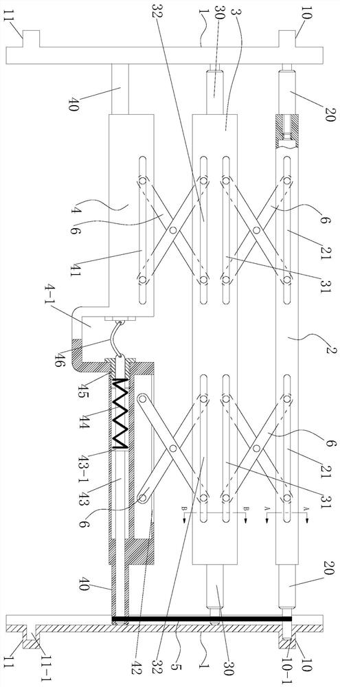
Skeleton structure of a car folding coat rack

A skeleton structure and folding technology, which is applied in the skeleton structure field of automobile folding coat racks, can solve problems such as no locking structure, messy placed items, and folded coat racks.

Active Publication Date: 2021-05-25
WUHU CHANGPENG AUTO PARTS
View PDF16 Cites 0 Cited by
  • Summary
  • Abstract
  • Description
  • Claims
  • Application Information

AI Technical Summary

Problems solved by technology

In addition, some foldable coat racks do not have a locking structure. Under the action of the inertial force of sudden braking or starting, the coat rack will be folded and the items placed on it will be messy.

Method used


Image

  • Skeleton structure of a car folding coat rack
  • Skeleton structure of a car folding coat rack
  • Skeleton structure of a car folding coat rack

Examples


Embodiment 1

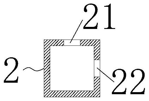
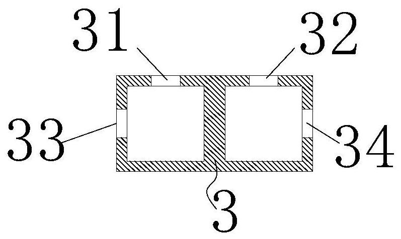
[0024] The skeleton structure of the car folding coat rack, when some higher items need to be installed in the trunk of the car, only the "U" groove 4-1 in the middle of the outer slide bar 4 is held by hand, and then the fingers are hooked Elastic resin sheet 46 uses very little force, and this moment latch lever 43 further compresses compression spring 44 by retaining shoulder 43-1, until latch lever 43 breaks away from hinge hole two 11-1 completely, at this moment in the elasticity of rubber band 5 Under the force, the outer sliding bar 4 is pulled toward the inner fixing bar 2, at the same time, the middle sliding bar 3 approaches the inner fixing bar 2, and the outer sliding bar 4 approaches the middle sliding bar 3, realizing the middle sliding bar 3 and the inner fixing bar 2. Folding and storage of the outer sliding rod 4; since the top of the inner fixing rod 2 is provided with a top long groove 21, and the side is provided with a side long groove 1 22, the top of the...

Embodiment 2

[0026]On the basis of embodiment 1, when some items need to be placed on the coat rack of the car, only the "U" groove 4-1 in the middle part of the outer slide bar 4 needs to be held by hand and pulled outward, and then overcome the rubber band 5, the outer slide bar 4 slides outward along the guide rail 1 until the latch bar 43 slides to the position of hinge hole 2 11-1 along with the outer slide bar 4, because the outer slide bar 4 is provided with a latch bar 43, the latch rod 43 is provided with a shoulder 43-1, the latch rod 43 is covered with a compression spring 44, the inner end of the outer sliding rod 4 is screwed to the end sleeve 45, and one end of the compression spring 44 is in contact with the shoulder 43-1 , the other end is in contact with the end sleeve 45, so under the elastic restoring force of the compression spring 44, the latch rod 43 is pushed outward by the shoulder 43-1, and inserted into the hinge hole 11-1 in the hinge seat 2 11, At the same time,...


PUM


Abstract

The invention discloses a skeleton structure of an automobile folding coat rack, which comprises a guide rail, an inner fixing rod, a middle sliding rod, an outer sliding rod and a rubber band. The other end of the guide rail is provided with hinge seat 2, the two ends of the inner fixing rod are screwed together with end shaft 1, and end shaft 1 is inserted into hinge hole 1, the two ends of the middle sliding rod are screwed together with end shaft 2, and end shaft 2 is embedded in the guide rail inside, and can slide in the guide rail, there are sliding shafts at both ends of the outer sliding rod, and the sliding shaft can slide in the guide rail, one end of the rubber band is sleeved on the end shaft one, and the other end is sleeved on the sliding shaft, the inner of the outer sliding rod There is a latch rod, a compression spring is set on the latch rod, the inner end of the outer sliding rod is screwed into the end sleeve, and a "U"-shaped groove is arranged in the middle of the outer sliding rod, and an elastic resin sheet is arranged in the "U"-shaped groove, and The two ends of the elastic resin sheet are respectively hinged with the end of the latch rod, which realizes the natural locking of the folding storage and unfolding of the coat rack, avoids automatic folding caused by inertial force, saves effort when unfolding, and is easy to operate.

Description

technical field [0001] The invention belongs to the technical field of automobile interior decoration components, in particular, the invention relates to a skeleton structure of an automobile folding coat rack. Background technique [0002] According to the configuration of the functional parts on the coat rack, different coat rack structures need to be selected, which can be integral or split. Passengers usually place some items on the coat rack, so there are certain requirements for the strength of the coat rack, and the coat rack is used as an interior part separating the passenger compartment and the luggage compartment. [0003] The current coat rack generally adopts one-time molding, the base material and fabric are directly stretched and formed, and the required final product is obtained after die-cutting, which is an integrated non-foldable structure. In the trunk of a car, sometimes you need to put some taller items, you need to fold and store the coat rack, when y...

Claims


Application Information

Patent Timeline
Patent Type & Authority Patents(China)
IPC IPC(8): B60R7/10
CPCB60R7/10
Inventor 束小东黄金金
Owner WUHU CHANGPENG AUTO PARTS
Learn More