Elevator guide rail alignment device and elevator guide rail alignment method
A technology of elevator guide rails and guide rails, which is applied in transportation, packaging, elevators, etc., can solve the problems of high proficiency and time-consuming, and achieve the effect of automatic positioning of high-precision guide rails
- Summary
- Abstract
- Description
- Claims
- Application Information
AI Technical Summary
Problems solved by technology
Method used
Image
Examples
Embodiment approach 1
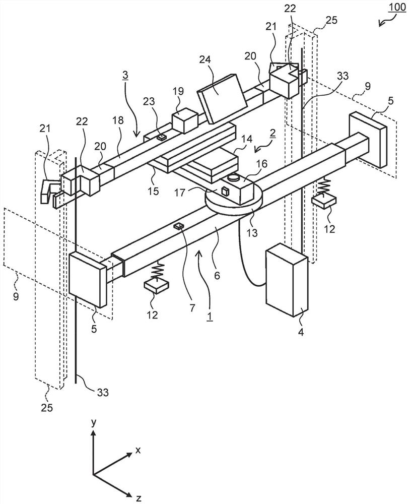
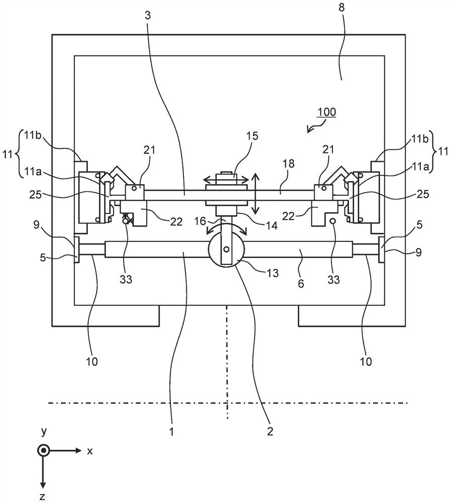
[0035] figure 1 It is a perspective view of an elevator guide rail centering device according to Embodiment 1 of the present invention. in addition, figure 2 Yes figure 1 The top view of the elevator guide rail alignment device shown.
[0036] (1-1) Structure of elevator guide rail alignment device 100
[0037] like figure 1As shown, the elevator guide rail core alignment device 100 according to the first embodiment includes a jig support portion 1 , a positioning mechanism 2 , a jig 3 , and a control device 4 . refer to figure 1 and figure 2 Next, the structure of the elevator guide rail core alignment device 100 will be described.
[0038] (1-1-1) Jig support part 1
[0039] The jig support unit 1 includes abutment plates 5 at both ends, beams 6 , and operation buttons 7 for operating each part of the jig support unit 1 .
[0040] The abutment plate 5 is a plate for abutting against a plate portion (or beam portion, wall portion) 9 provided at the bracket mounting...
Embodiment approach 2
[0119] Figure 9 It is a plan view of an elevator guide rail centering device according to Embodiment 2 of the present invention.
[0120] (2-1) Structure of elevator guide rail alignment device 200
[0121] Figure 9 The shown elevator guide rail centering device 200 is the same as the elevator guide rail centering device 100 involved in Embodiment 1 (refer to figure 1 ) is different in that the mechanism that presses out the abutment plate 5 of the fixture supporting part 1 doubles as the parallel direction positioning device 15 in the x-axis direction; and the two linear motions connected between the fixture supporting part 1 and the fixture 3 The actuators 160a, 160b (linear motion actuator 160) are also used as the rotation angle positioning device 13 and the parallel direction positioning device 14 in the z-axis direction.
[0122] The linear motion actuator 160 can adopt the same two-stage structure as the parallel direction positioning device 14 described in Embodim...
Embodiment approach 3
[0143] Figure 11 It is a plan view of the elevator guide rail centering apparatus concerning Embodiment 3 of this invention. Figure 11 The shown elevator guide rail centering device 300 is compared with the elevator guide rail centering device 200 involved in Embodiment 2 (refer to Figure 9 ) differs in the connection method of the two linear motion actuators 160a, 160b disposed between the jig support portion 1 and the jig 3 . On the other hand, the same point as Embodiment 2 lies in that the mechanism for pushing out the abutment plate 5 of the jig supporting part 1 is also used as the parallel direction positioning device 15 in the x-axis direction; and it is connected between the jig supporting part 1 and the jig 3 The two linear motion actuators 160a and 160b are also used as the rotation angle positioning device 13 and the parallel direction positioning device 14 in the z-axis direction.
[0144] according to Figure 11 , Two rotation shafts 170a, 170b (rotation sh...
PUM
 Abstract
Description
Claims
Application Information
 - R&D
- Intellectual Property
- Life Sciences
- Materials
- Tech Scout
- Unparalleled Data Quality
- Higher Quality Content
- 60% Fewer Hallucinations
Browse by: Latest US Patents, China's latest patents, Technical Efficacy Thesaurus, Application Domain, Technology Topic, Popular Technical Reports.
© 2025 PatSnap. All rights reserved.Legal|Privacy policy|Modern Slavery Act Transparency Statement|Sitemap|About US| Contact US: help@patsnap.com


