Attitude control method of underwater vehicle based on air film drag reduction technology
An underwater vehicle and attitude control technology, which is applied to the types of weapons, ship construction, transportation and packaging, etc., can solve the problems of uncontrollable navigation attitude and damage to the overall structure of the air film
- Summary
- Abstract
- Description
- Claims
- Application Information
AI Technical Summary
Problems solved by technology
Method used
Image
Examples
Embodiment 1
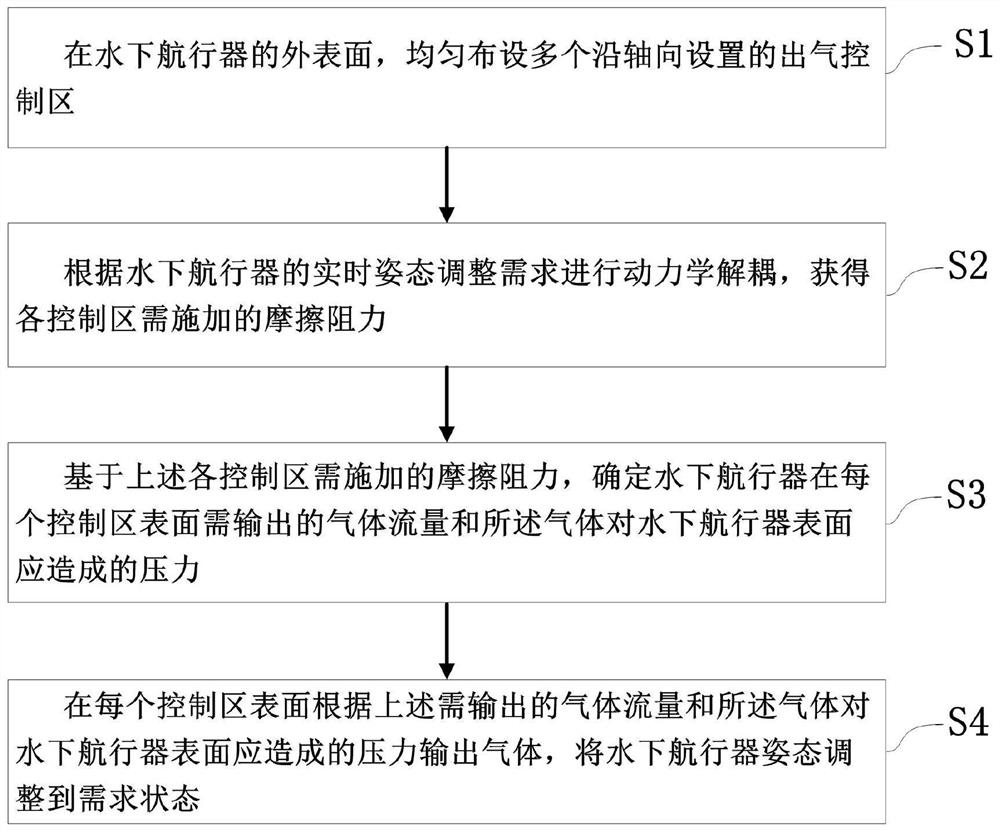
[0066] A specific embodiment of the present invention discloses a method for controlling the attitude of an underwater vehicle based on air film drag reduction technology, such as figure 1 shown, including the following steps:
[0067] S1. On the outer surface of the underwater vehicle, evenly arrange a plurality of air outlet control areas arranged along the axial direction;
[0068] S2. Perform dynamic decoupling according to the real-time attitude adjustment requirements of the underwater vehicle to obtain the frictional resistance to be applied in each control area;
[0069] S3. Based on the frictional resistance to be applied in the above-mentioned control areas, determine the gas flow rate that the underwater vehicle needs to output on the surface of each control area and the pressure that the gas should cause on the surface of the underwater vehicle;
[0070] S4. Output gas on the surface of each control area according to the above-mentioned gas flow rate to be output ...
Embodiment 2
[0073] Optimizing on the basis of Embodiment 1, step S1 can be further refined into the following steps:
[0074] S11. According to the enveloping moment required by the static force and maneuverability of the underwater vehicle, combined with the number of control areas, the design radian of the control area, and the radius of the underwater spacecraft, determine the length of the control area. Specifically, the length L of each control zone is determined by the following formula
[0075]
[0076] In the formula, M is the envelope moment input during design, C f is the drag coefficient, α is the preset radian of the control area, and d is the radius of the underwater vehicle.
[0077] S12. Determine the area of the control area of each control area according to the length of the control area. Specifically, it can be calculated by the following formula
[0078] S=Ldα
[0079] S13. On the outer surface of the underwater vehicle, uniformly lay out the number of contro...
Embodiment 3
[0114] The invention also discloses an underwater vehicle attitude control device adopting the method described in Embodiment 1, which includes an integrated controller and a plurality of air outlet control areas uniformly arranged on the outer surface of the underwater vehicle; The area is equipped with gas generation and control devices.
[0115] The integrated controller is used to perform dynamic decoupling according to the real-time attitude adjustment requirements of the underwater vehicle, obtain the frictional resistance to be applied in each control area, and then determine the gas flow rate that the underwater vehicle needs to output on the surface of each control area As well as the pressure that the gas should cause on the surface of the underwater vehicle, the gas flow and the pressure are sent to the gas generation and control device in the corresponding control area.
[0116] The gas generation and control device is used to control the generated gas to be discha...
PUM
 Abstract
Description
Claims
Application Information
 - R&D
- Intellectual Property
- Life Sciences
- Materials
- Tech Scout
- Unparalleled Data Quality
- Higher Quality Content
- 60% Fewer Hallucinations
Browse by: Latest US Patents, China's latest patents, Technical Efficacy Thesaurus, Application Domain, Technology Topic, Popular Technical Reports.
© 2025 PatSnap. All rights reserved.Legal|Privacy policy|Modern Slavery Act Transparency Statement|Sitemap|About US| Contact US: help@patsnap.com


