Supercharge Your Innovation With Domain-Expert AI Agents!

Design method of telescopic support rod, passive telecentric mechanism and support rod thereof

A technology of telescopic support rods and design methods, applied in the field of medical equipment, can solve problems such as difficult operation, unbalance, and constant size

Active Publication Date: 2021-06-04
SHENZHEN INST OF ADVANCED TECH CHINESE ACAD OF SCI
View PDF12 Cites 0 Cited by
  • Summary
  • Abstract
  • Description
  • Claims
  • Application Information

AI Technical Summary

Problems solved by technology

The most common telescopic support rods generally use a friction block to generate friction, and the size remains unchanged during the stretching process, which leads to the operation changing due to the excessive friction of the friction rod when it is dragged and rotated. It is difficult to obtain, or because the friction force of the friction force rod is small and cannot completely overcome the gravity of the passive telecentric mechanism, an imbalance occurs, or because the friction force of the friction force rod can only make the passive telecentric mechanism move in a certain section of the stroke. The apocentric point is in balance, while at other travel positions there is an imbalance due to the free fall of the apocentric point

Method used


Image

  • Design method of telescopic support rod, passive telecentric mechanism and support rod thereof
  • Design method of telescopic support rod, passive telecentric mechanism and support rod thereof
  • Design method of telescopic support rod, passive telecentric mechanism and support rod thereof

Examples


Embodiment 1

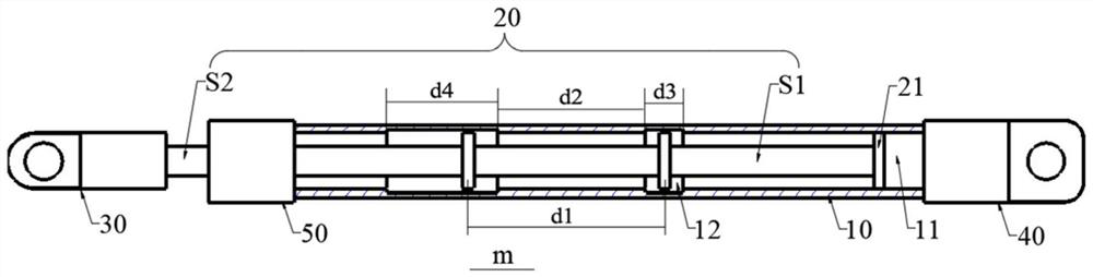
[0031] figure 1 It is a structural schematic diagram of an exemplary telescopic support rod of the present invention.

[0032] refer to figure 1 As shown, the exemplary telescopic support rod m of the present invention includes a first support rod 10 and a second support rod 20 that are socketed and can slide relative to each other. A telescopic channel 11 is axially provided in the first support rod 10, and the telescopic channel 11 An accommodating groove 12 is provided in the inner cavity, and the second support rod 20 has opposite first end S1 and second end S2. The first end S1 is provided with a friction block 21, and the first end S1 extends into the telescopic channel 11 to enable The friction block 21 is in frictional contact with the inner wall of the telescopic channel 11, and the second end S2 extends out of the first pole 10. During the relative sliding process of the first pole 10 and the second pole 20, the friction block 21 breaks away from or enters the accom...

Embodiment 2

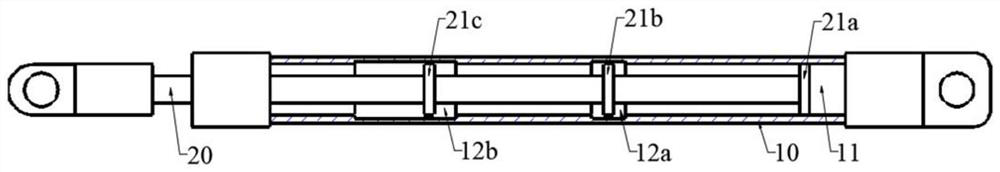
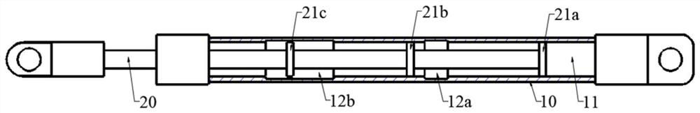
[0039] This embodiment proposes a specific implementation based on the telescopic support rod m of Embodiment 1, as shown in FIG. 2 , Figure 2(a) ~ Figure 2(c) It is a schematic diagram of the relative sliding process of the first pole and the second pole in the telescopic support pole of this embodiment.

[0040] Specifically, as shown in FIG. 2(a), two accommodating grooves 12 are arranged at intervals along the axial direction of the first strut 10 in this embodiment, which are respectively the first accommodating groove 12a and the second accommodating groove 12b, and The lengths of the first accommodating groove 12a and the second accommodating groove 12b increase sequentially. Three friction blocks 21 are provided at intervals along the axial direction of the second support rod 20 , which are respectively a first friction block 21 a , a second friction block 21 b and a third friction block 21 c .

[0041] Continuing to refer to Fig. 2 (a), when the first strut 10 and t...

Embodiment 3

[0046] This embodiment provides a passive telecentric mechanism including the telescopic support rod in Embodiment 1 or Embodiment 2 above, image 3 It is a schematic structural diagram of an exemplary passive telecentric mechanism in this embodiment.

[0047] refer to image 3 As shown, the passive telecentric mechanism of this embodiment includes a frame 1, a rotating arm group 2, a moving arm group 3, an imaging device 4, and the telescopic support rod m in the above-mentioned embodiment 1 or embodiment 2. The rotating arm group 2 includes connecting rod a and connecting rod b arranged in parallel, and the moving arm group 3 includes connecting rod c and connecting rod d arranged in parallel, and one end of connecting rod a and connecting rod b is respectively at hinge point A and hinge point C It is hinged with the frame 1, and the other end is hinged with the connecting rod c and the connecting rod d at the same time, wherein the connecting rod d forms hinge point B and ...


PUM


Abstract

The invention discloses a design method of a telescopic support rod, a passive telecentric mechanism and a support plate thereof. The telescopic support rod includes a first support rod and a second support rod which are socketed and can slide relative to each other. The inner shaft of the first support rod is A telescopic passage is provided in the direction, and an accommodating groove is provided in the recess of the telescopic passage. The second support rod has a first end and a second end opposite to each other. The first end is provided with a friction block, and the first end extends into the telescopic passage to make the The friction block is in frictional contact with the inner wall of the telescopic channel, and the second end protrudes from the first support rod. During the relative sliding process of the first support rod and the second support rod, the friction block breaks away from or enters the accommodating groove to change the relationship between the second support rod and the first support rod. Friction between a rod. The design method of the telescopic support rod, the passive telecentric mechanism and the support rod thereof of the present invention uses a plurality of friction blocks to alternately contact with the inner wall of the telescopic channel at different positions, so that the support rod produces different frictional forces at different telescopic positions, which can Effectively balance the changing gravitational moment of the passive telecentric mechanism to achieve the effect of pulling and stopping.

Description

technical field [0001] The invention relates to the field of medical devices, and specifically relates to a telescopic support rod, a passive telecentric mechanism and a design method for the support rod. Background technique [0002] During minimally invasive surgery, doctors use telecentric mechanisms to hold imaging devices such as endoscopes or ultrasound endoscopes to perform surgical image guidance tasks. The telecentric mechanism used generally adopts a parallelogram structure, which can be dragged by hand to realize the movement of the telecentric point, including forward and backward pitch rotation, left and right swing, spin and translation, etc., so that the imaging device can take pictures or form images from different spatial postures in the body the goal of. This parallelogram telecentric mechanism dragged by hand is also called passive parallelogram telecentric mechanism or passive telecentric mechanism. [0003] The pitching rotation of the telecentric poin...

Claims


Application Information

Patent Timeline
Patent Type & Authority Patents(China)
IPC IPC(8): A61B90/50
CPCA61B90/50A61B2090/5025A61B2090/506
Inventor 熊璟刘勇夏泽洋
Owner SHENZHEN INST OF ADVANCED TECH CHINESE ACAD OF SCI
Features
  • R&D
  • Intellectual Property
  • Life Sciences
  • Materials
  • Tech Scout
  • Unparalleled Data Quality
  • Higher Quality Content
  • 60% Fewer Hallucinations
Learn More