A steel-concrete one-way composite beam-column joint

A technology of beam-column joints and concrete, applied in buildings, building components, building structures, etc., can solve problems affecting the seismic performance of structures, large tensile stress at the lower flange of steel beams, and reduce the deformation capacity of composite beams, etc., so as to facilitate popularization Effects of using, guaranteeing strength, and weakening combined effects

Active Publication Date: 2021-07-02
CHANGAN UNIV
View PDF0 Cites 0 Cited by
  • Summary
  • Abstract
  • Description
  • Claims
  • Application Information

AI Technical Summary

Problems solved by technology

[0003] However, under the action of positive moment load, the concrete slab of this type of composite beam is under compression, while most of the steel beam is under tension. Although the advantages of the two materials of concrete and steel can be brought into play, the concrete wing plate can also be used for steel beams. It plays a very good lateral restraint effect and avoids the lateral torsional instability of the steel beam, but this makes the tensile stress of the lower flange of the steel beam too large when the positive bending moment acts. The welding part of the lower flange of the beam is often cracked and damaged, which reduces the deformation capacity of the composite beam and affects the seismic performance of the structure
To sum up, due to the combination effect, the centroid axis of the T-shaped steel-concrete composite beam section moves upward. When the positive bending moment acts, the weld of the lower flange of the H-shaped steel beam is damaged due to excessive tensile stress, and if If the stud connector is not used, the steel beam and the concrete will not have a combined effect. Although the above problems can be improved, the problem of vertical pull-out resistance of the concrete slab appears.

Method used


Image

  • A steel-concrete one-way composite beam-column joint
  • A steel-concrete one-way composite beam-column joint
  • A steel-concrete one-way composite beam-column joint

Examples


Embodiment Construction

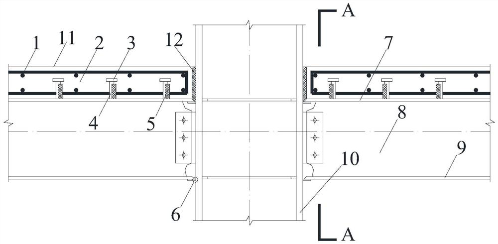
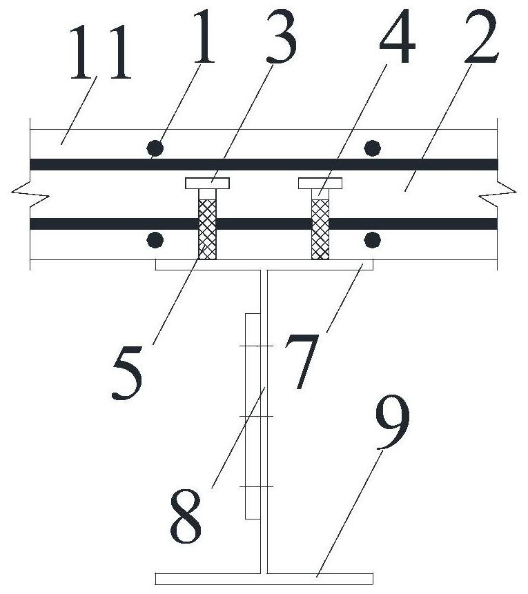
[0033] like Figure 1 to Figure 7 As shown, the present invention includes a steel column 10, an H-shaped steel beam fixedly connected to the steel column 10 and a concrete slab 11 arranged on the H-shaped steel beam, and the H-shaped steel beam includes an upper flange plate 7 of the H-shaped steel beam , the H-shaped steel beam lower flange plate 9, and the H-shaped steel beam web 8 arranged between the H-shaped steel beam upper flange plate 7 and the H-shaped steel beam lower flange plate 9, the H-shaped steel beam upper flange plate 7 is close to A one-way shear connector is prefabricated on the slab section of the steel column 10 and located in the concrete slab 11, and a shear cushion 12 is provided at the contact position between the concrete slab 11 and the steel column 10, and the height of the shear cushion 12 is the same as that of the concrete slab. 11 have the same thickness, the top of the shear buffer pad 12 is flush with the upper surface of the concrete slab 1...


PUM


Abstract

The invention discloses a steel-concrete unidirectional composite beam-column node, which comprises a steel column, an H-shaped steel beam, a concrete slab, and a unidirectional shear-resistant connector. A shear buffer pad is arranged at the contact position between the concrete slab and the steel column. The height of the shear buffer pad is equal to the thickness of the concrete slab, and the one-way shear connectors include the studs welded on the top of the upper flange plate of the H-shaped steel beam and the one-way shear buffer block with the studs facing the side of the steel column. The anti-shear buffer block is arranged on the body of the stud, and the height of the stud is smaller than the thickness of the concrete slab. The invention is novel in design, and by arranging a one-way shear connector at the upper flange plate of the H-shaped steel beam, the combination effect when the positive bending moment acts is weakened, and the centroid axis of the combined section moves downward when the positive bending moment acts, thereby Reduce the tensile stress of the welding part of the lower flange of the H-shaped steel beam to avoid damage, and at the same time ensure the pullout performance of the one-way shear connector and the combined effect when the negative bending moment acts, the structure is simple, and the construction method is simple .

Description

technical field [0001] The invention belongs to the technical field of building structures, and in particular relates to a steel-concrete one-way composite beam-column joint. Background technique [0002] Steel-concrete composite beams can be divided into outsourcing concrete composite beams and T-shaped composite beams according to the cross-sectional form. The steel beams of T-shaped composite beams are exposed, and the steel beams and concrete flanges are combined by shear connectors. The T-shaped steel-concrete composite beam section is generally composed of three parts: steel beam, concrete wing plate and shear connector. Among them, the shear connector is the basis for the joint work of the steel beam and the concrete wing plate, which is mainly used to bear the longitudinal shear force between the reinforced concrete wing plate and the steel beam contact surface, and resist the relative slip between the two; in addition , it also has the function of resisting the lif...

Claims


Application Information

Patent Timeline
Patent Type & Authority Patents(China)
IPC IPC(8): E04B1/24E04B1/58E04B5/32
CPCE04B1/2403E04B5/32
Inventor 吴函恒郭涛隋璐续丛丛
Owner CHANGAN UNIV
Why Eureka
Try Eureka