Check patentability & draft patents in minutes with Patsnap Eureka AI!

A commutation error compensation method for high-speed brushless DC motor

A brush DC motor and error compensation technology, which is applied in the field of commutation error compensation, can solve the problems of adding hardware equipment, etc., and achieve the effects of reducing complexity, compensating commutation errors, and avoiding current sensors

Active Publication Date: 2019-09-06
TIANJIN UNIV
View PDF3 Cites 7 Cited by
  • Summary
  • Abstract
  • Description
  • Claims
  • Application Information

AI Technical Summary

Problems solved by technology

Among them, some scholars use the difference of the motor phase voltage before and after the non-commutation phase as the error information of the commutation point, but this method needs to construct a virtual neutral point to obtain the phase voltage, which will increase the hardware equipment of the system
In order to reduce the hardware equipment, some scholars use the motor phase current to obtain the error information of the commutation point. This method analyzes the influence of the lead and lag commutation on the phase current, and points out that in the case of lead and lag commutation, the non-commutation phase current There is a sudden change before and after the commutation point, so the difference between the phase current before and after the commutation point is used as the deviation of the system, and the phase compensation angle is used as the controlled quantity to establish an adaptive compensation regulator to correct the commutation point phase, this method can effectively improve the commutation accuracy, but requires a higher precision current sensor

Method used


Image

  • A commutation error compensation method for high-speed brushless DC motor
  • A commutation error compensation method for high-speed brushless DC motor
  • A commutation error compensation method for high-speed brushless DC motor

Examples


Embodiment Construction

[0030] A commutation error compensation method for a high-speed brushless DC motor of the present invention will be described in detail below with reference to the embodiments and the accompanying drawings.

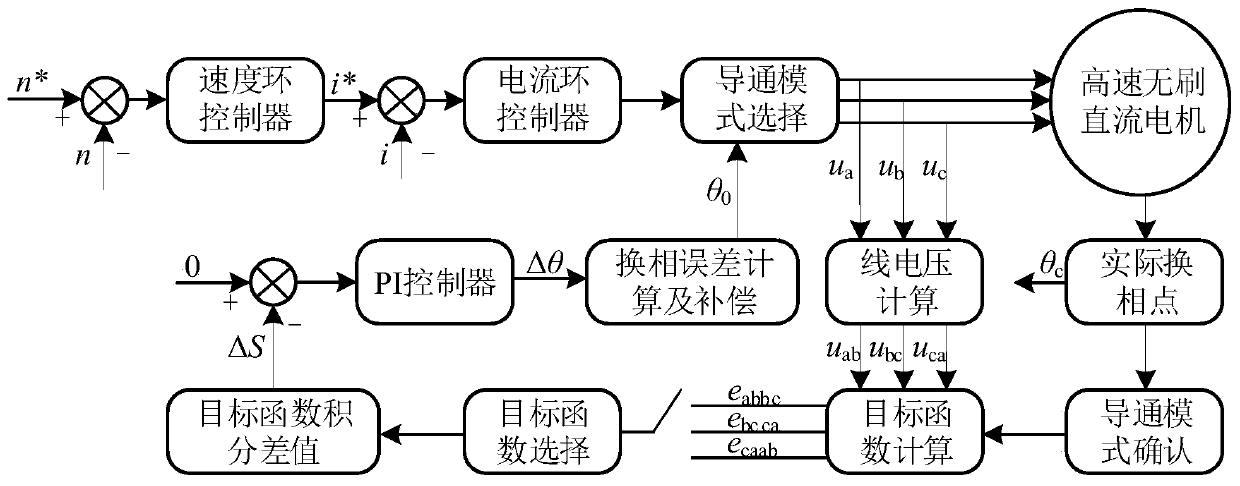
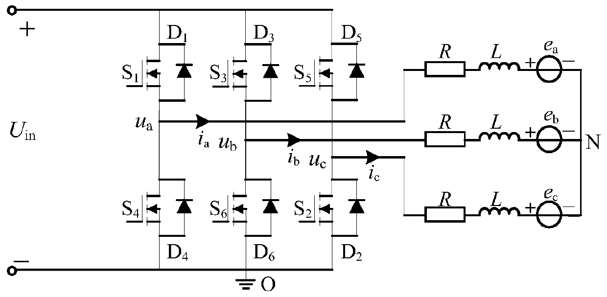
[0031] A control block diagram of a high-speed brushless DC motor used in a commutation error compensation method for a high-speed brushless DC motor of the present invention is as follows figure 1 As shown, the system hardware part includes a DC power supply, a high-speed brushless DC motor, a three-phase inverter bridge and a microcontroller. Among them, the microcontroller is responsible for obtaining the rotor position information and the commutation point signal, and then compensates the phase of the commutation point.

[0032] A commutation error compensation method for a high-speed brushless DC motor of the present invention comprises the following steps:

[0033] 1) The high-speed brushless DC motor system uses the voltage sensor to obtain the three-phase phase v...


PUM


Abstract

The invention proposes a commutation error compensation method for a high-speed brushless DC motor. The commutation error compensation method comprises the steps of calculating to obtain a linear counter potential difference expression, namely a target function, of a motor according to a phase voltage expression of the motor obtained by acquisition of a voltage sensor, and setting corresponding target functions for six conduction modes of the motor; determining two conduction modes before and after an estimated commutation point of the motor and the target functions corresponding to the two conduction modes; and selecting the same electric angle range to perform integral operation on the target functions around the estimated commutation point, and obtaining corresponding integral values S1and S2 under the two conduction modes and difference Delta S between the S1 and the S2. A relation between the Delta S and an error Delta Theta of an angle where the estimated commutation point is located and an angle where an actual commutation point is located can be obtained according to the expression of Delta S, so that a commutation error angle is compensated. Only the phase voltage information is needed to be known, the number of a passive device is reduced, and the complexity of the system is reduced.

Description

technical field [0001] The invention relates to a commutation error compensation method. In particular, it relates to a commutation error compensation method for a high-speed brushless DC motor suitable for drive control of the high-speed brushless DC motor. Background technique [0002] With the improvement of the performance of power electronic devices and the reduction of cost, the application of high-performance permanent magnet materials and the development of computer technology, high-speed brushless DC motors are used in applications with high speed, high transmission accuracy and high requirements for equipment quality and space. Widely used in, such as centrifugal air compressors, vacuum pumps, turbomolecular pumps, flywheel energy storage systems, spindle motors and attitude control and other directions. [0003] In order to make the high-speed brushless DC motor run smoothly and normally, it is necessary to obtain the position information of the rotor in real tim...

Claims


Application Information

Patent Timeline
Patent Type & Authority Applications(China)
IPC IPC(8): H02P6/182H02P6/12
CPCH02P6/12H02P6/182
Inventor 夏长亮程昱曹彦飞李新旻史婷娜陈炜
Owner TIANJIN UNIV
Features
  • R&D
  • Intellectual Property
  • Life Sciences
  • Materials
  • Tech Scout
  • Unparalleled Data Quality
  • Higher Quality Content
  • 60% Fewer Hallucinations
Learn More