
Infrared confocal wide-angle lens

A wide-angle lens and infrared confocal technology, applied in the field of infrared confocal wide-angle lens, can solve the problems of increased weight, increased cost, unfavorable promotion and use, etc., and achieve the effect of reducing weight and cost, good infrared confocal, and realizing large aperture

Pending Publication Date: 2019-09-10
UNION OPTECH
View PDF0 Cites 8 Cited by
  • Summary
  • Abstract
  • Description
  • Claims
  • Application Information

AI Technical Summary

Problems solved by technology

[0004] At present, the monitoring industry has put forward new requirements for the wide-angle fixed-focus lens used, that is, it needs to meet the infrared confocal, and at the same time, it must achieve a large aperture and a large target area to meet the high-definition imaging requirements for day and night use and poor lighting conditions. The existing lenses that can meet this requirement basically use a large number of glass lenses, and even use glass aspheric surfaces, which increases the weight and cost, which is not conducive to popularization and use.

Method used


Image

  • Infrared confocal wide-angle lens
  • Infrared confocal wide-angle lens
  • Infrared confocal wide-angle lens

Examples


Embodiment Construction

[0047] The specific implementation manners of the present invention will be described in further detail below in conjunction with the accompanying drawings.

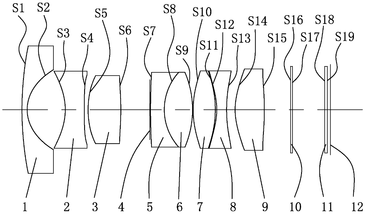
[0048] like figure 1 As shown, an infrared confocal wide-angle lens is sequentially provided with: a front lens group, a diaphragm 4, a rear lens group, a filter 10, a protective glass 11 and a photosensitive chip 12 from the object side to the image side;

[0049] The refractive power of the front lens group is negative, and the front lens group includes:

[0050] The first lens 1, the refractive power of the first lens 1 is negative, the side of the first lens 1 facing the object side is a convex surface, and the side facing the image side is a concave surface;

[0051] The second lens 2, the refractive power of the second lens 2 is negative, and both surfaces of the second lens 2 are concave;

[0052] The third lens 3, the refractive power of the third lens 3 is positive, and both surfaces of the third lens 3 are co...


PUM


Abstract

The invention discloses an infrared confocal wide-angle lens. The infrared confocal wide-angle lens comprises in order from an object side to an image side: a front lens group, a diaphragm, a rear lens group, an optical filter, protection glass and a photosensitive chip. The focal power of the front lens group is negative, and the front lens group comprises: a first lens, wherein the focal power of the front lens is negative, one surface, facing the object side, of the front lens is a convex surface, and one surface, facing the image side, of the front lens is a concave surface; a second lens,wherein the focal power of the second lens is negative, the two surfaces of the second lens are both concave surfaces; and a third lens, wherein the focal power of the third lens is positive, and thetwo surfaces of the third lens are both convex surfaces. The focal power of the rear lens group is positive, and the rear lens group comprises: a fourth lens, wherein the focal power of the fourth lens is negative, one surface, facing the object side, of the fourth lens is a convex surface, and one surface, facing the image side, of the fourth lens is a concave surface; a fifth lens, wherein thefocal power of the fifth lens is positive, and the two surfaces of the fifth lens are both convex surfaces; a sixth lens, wherein the focal power of the sixth lens is positive, and the two surfaces ofthe sixth lens are both convex surfaces; a seventh lens, wherein the focal power of the seventh lens is negative, and the two surfaces of the seventh lens are both concave surfaces; and an eighth lens, wherein the focal power of the eighth lens is positive, and the two surfaces of the eighth lens are both convex surfaces. Each lens adopts a concave-convex combined structure, and can better achieve infrared confocal.

Description

[0001] 【Technical field】 [0002] The invention relates to the technical field of optical lenses, in particular to an infrared confocal wide-angle lens. [0003] 【Background technique】 [0004] At present, the monitoring industry has put forward new requirements for the wide-angle fixed-focus lens used, that is, it needs to meet the infrared confocal, and at the same time, it must achieve a large aperture and a large target area to meet the high-definition imaging requirements for day and night use and poor lighting conditions. The existing lenses that can meet this requirement basically use a relatively large number of glass lenses, and even use glass aspheric surfaces, which increases the weight and cost, which is not conducive to popularization and use. [0005] Therefore, the present invention just produces based on above deficiency. [0006] 【Content of invention】 [0007] The object of the present invention is to overcome the deficiencies of the prior art and provide an...

Claims


Application Information

Patent Timeline
IPC IPC(8): G02B13/00G02B13/06G02B13/14G02B1/00
CPCG02B13/0045G02B13/06G02B13/14G02B1/00
Inventor 罗吉祥肖明志李建华
Owner UNION OPTECH
Learn More