A control device for ion implantation in wafer production

An ion implantation and control device technology, which is applied in the manufacture of semiconductor/solid-state devices, discharge tubes, electrical components, etc., and can solve the problems of ion output dispersion, difficulty in direct irradiation, and damage to the output port.

Active Publication Date: 2021-04-20
ANHUI XINDALU SPECIAL PAINT CO LTD
View PDF2 Cites 0 Cited by
  • Summary
  • Abstract
  • Description
  • Claims
  • Application Information

AI Technical Summary

Problems solved by technology

[0006] In order to solve the problem that the above-mentioned technology has a certain degree of heat due to the direct ion implantation, when the output port is output through the focused output port for a long time, the output port will be damaged, which will easily cause the ions to scatter during output, and it is difficult to directly irradiate to the corresponding position.

Method used


Image

  • A control device for ion implantation in wafer production
  • A control device for ion implantation in wafer production
  • A control device for ion implantation in wafer production

Examples


Embodiment

[0030] as attached figure 1 to attach Figure 8 Shown:

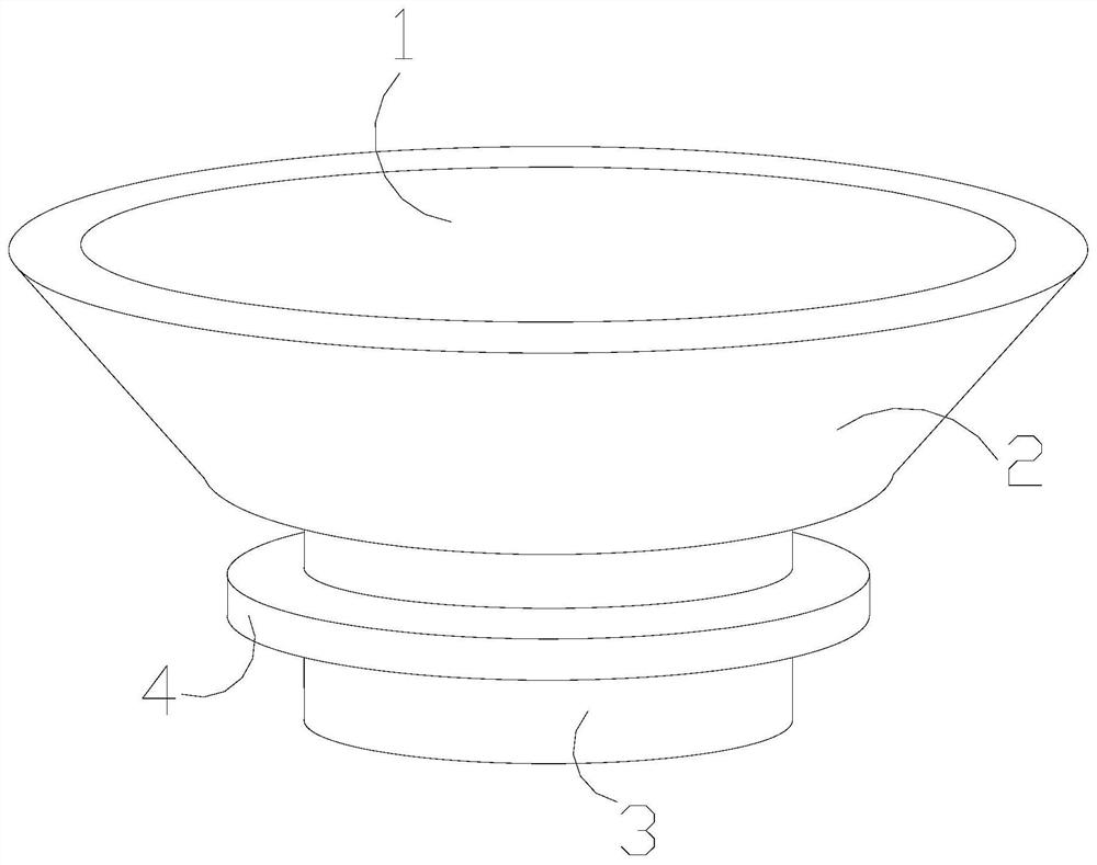
[0031] The invention provides a control device for ion implantation in wafer production, the structure of which includes a movable channel 1 , a connecting operation head 2 , an ion calibration output port 3 , and a guard ring 4 .

[0032] The movable channel 1 is installed inside the connecting operation head 2, the bottom end of the connecting operation head 2 is connected to the top end of the ion calibration output port 3, and the guard ring 4 is nested on the outer surface of the ion calibration output port 3 and is located on the same axis. heart.

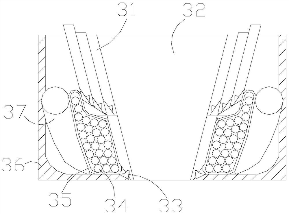
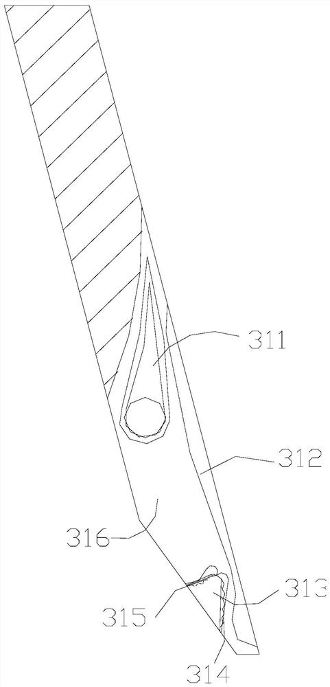
[0033] The ion proofreading output port 3 includes a proofreading mouth rod 31, a direct shot path 32, a complete buckle 33, a flexible pressure ball 34, an integral capsule 35, a partition 36, and a directional ejector rod 37, and the proofreading mouth rod 31 is located at the straight shot path 32 On the left and right sides, the complete buckle 33 and the partiti...


PUM


Abstract

The invention discloses a control device for ion implantation in wafer production. Its structure includes a movable channel, a connection operation head, an ion calibration output port, and a guard ring. The movable channel is installed inside the connection operation head, and the ion calibration output port includes a calibration When the ion implantation port is damaged, the former will fall, and the latter main rod will slide down. The boomerang is stretched by the force of the space, and its lubricating layer assists its corners to slide to both sides. When the boomerang is stretched, the bending direction limiting rod will be squeezed, and the gap between the hook and the fixed column Positioning, the top shell will push the overall capsule, and the external pressure arc inside the overall capsule will be forced to make it stand on the surface of the new main rod and fix it. , Make up the backup in time to prevent mistakes during the operation, and overhaul it after the operation.

Description

technical field [0001] The invention belongs to the field of semiconductors, and more specifically relates to a control device for ion implantation used in wafer production. Background technique [0002] There is a step in the process of wafer production that requires ion implantation. After the ions are accelerated internally, they are located in the vertical direction and pass through the corresponding position of the output port. They are directly irradiated on the surface of the wafer. Ions will generate a certain amount of heat in the process of accelerating direct radiation. [0003] Based on the above inventors' discovery, the existing ion implantation control device for wafer production mainly has the following deficiencies, such as: [0004] Because there is a certain amount of heat in direct ion implantation, when the output port is output quickly through the focus for a long time, the output port will be damaged, which will easily cause the ions to scatter during...

Claims


Application Information

Patent Timeline
Patent Type & Authority Patents(China)
IPC IPC(8): H01J37/30H01J37/317H01L21/67
CPCH01J37/3002H01J37/3171H01J2237/31701H01L21/67011
Inventor 祁金发
Owner ANHUI XINDALU SPECIAL PAINT CO LTD
Why Eureka
Try Eureka