

Multi-bidirectional clutch automatic transmission and vehicle body
A two-way clutch, automatic transmission technology, applied in the direction of clutch, transmission, gear transmission, etc., can solve the problems of poor reliability at low speed, power lag, and slippage, so as to achieve a smooth and unobtrusive start of the car, and avoid serious power lag effect of the problem
- Summary
- Abstract
- Description
- Claims
- Application Information
AI Technical Summary
Problems solved by technology
Method used
Image


Examples
Embodiment 1
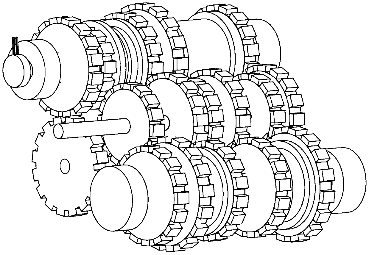
[0060] In a typical implementation of the present application, the seven gears are taken as an example to describe in detail; figure 1 , figure 2 As shown, it includes a gearbox housing, a first shaft 11, a second shaft 12, and a third shaft 13. The first shaft 11, the second shaft 12, and the third shaft 13 are parallel to each other, and the first shaft 11 is located at the second shaft 12. Between the three axis 13, the second axis 12 is below the first axis 11, and the three axis 13 is above the first axis 11;
[0061] Drive gear 9 and drive gear 10 are respectively installed on the leftmost side of the two or three shafts, and a passive differential gear 8 is installed below the first shaft. Drive gear 9 and drive gear 10 can transmit power to the passive gear. differential gear 8;
[0062] The first shaft is provided with second-speed driving gears, fourth-speed and sixth-speed driving gears, seventh-speed driving gears, third-speed driving gears, first-speed driving ...
Embodiment 2
[0098] In this embodiment, the third gear is taken as an example for illustration;
[0099] Three-speed gearbox such as image 3 As shown, it includes a gearbox housing, a first shaft, a second shaft, and a third shaft. The first shaft, the second shaft, and the third shaft are parallel to each other, and the first shaft is located between the second shaft and the third shaft. One driving gear is installed on the second shaft and three shafts, and a passive differential gear is installed under the first shaft. Both driving gears mesh with the differential gear to transmit power to the passive differential gear;
[0100] The first-speed driving gear, the second- and third-speed driving gears are sequentially arranged on the first shaft;
[0101] The driven idler gears of 1D and 3D gears are correspondingly arranged on the two shafts; a first two-way clutch is installed between the driven idler gears of 1D and 3D gears;
[0102] The driven idler gears of R and 2D gears are cor...
Embodiment 3
[0110] In this embodiment, 4 gears are taken as an example for illustration;
[0111] Four-speed gearbox such as Figure 4 As shown, it includes a gearbox housing, a first shaft, a second shaft, and a third shaft. The first shaft, the second shaft, and the third shaft are parallel to each other, and the first shaft is located between the second shaft and the third shaft. One driving gear is installed on the second shaft and three shafts, and a passive differential gear is installed under the first shaft. Both driving gears mesh with the differential gear to transmit power to the passive differential gear;
[0112] The first gear, the second and third gears are sequentially arranged on the first shaft; the fourth gear is the driving gear;
[0113] The driven idler gears of 1D and 3D gears are correspondingly arranged on the two shafts; a two-way clutch is installed between the driven idler gears of 1D and 3D gears;
[0114] Correspondingly provided with R, 2D, 4D gears driven...
PUM
 Abstract
Description
Claims
Application Information