
Rotary gravity unloading device

A gravity unloading and rotary technology, which is applied to the simulation device of space navigation conditions, transportation and packaging, space navigation equipment, etc., can solve the problem of insufficient unloading accuracy and achieve the effect of avoiding additional deformation

Active Publication Date: 2020-12-11
CHANGCHUN INST OF OPTICS FINE MECHANICS & PHYSICS CHINESE ACAD OF SCI
View PDF5 Cites 0 Cited by
  • Summary
  • Abstract
  • Description
  • Claims
  • Application Information

AI Technical Summary

Problems solved by technology

The unloading accuracy of the conventional gravity unloading device is not enough

Method used


Image

  • Rotary gravity unloading device
  • Rotary gravity unloading device
  • Rotary gravity unloading device

Examples


Embodiment Construction

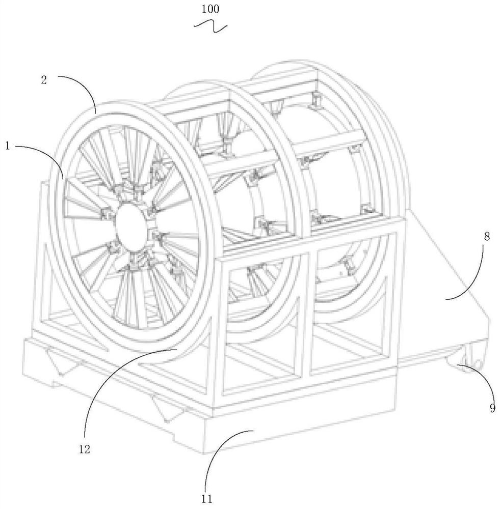
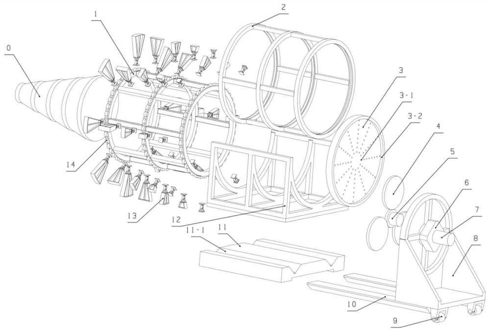
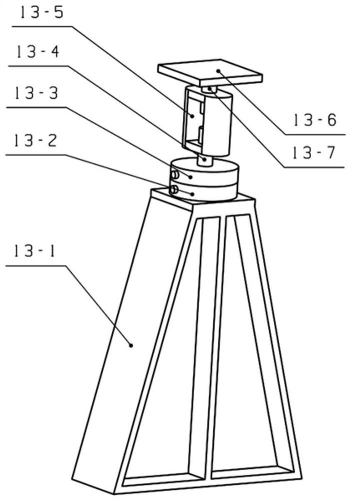
[0024] see Figure 1 to Figure 5 , the present invention provides a rotary gravity unloading device 100, including a supporting device, a plurality of combined loading frames and a driving device. The supporting device comprises a moving cage 1, a fixed cage 2 ring mounted on the moving cage 1, a cage bearing 14 connecting the moving cage 1 and the fixed cage 2, the moving cage 1 rotates along the fixed cage 2, and moves The cage 1 constitutes a pair of rotary kinematics with the fixed cage 2 through the cage bearing 14 . Furthermore, the support device also includes a U-shaped bracket 12 arranged on the fixed base 11 , and the U-shaped bracket 12 is used to support the fixed cage frame 2 .

[0025] The driving device includes a tooling backboard 3 arranged at one end of the moving cage frame 1, a planetary gear train (comprising an internal ring gear 3-2, three planetary gears 4, and a sun gear 5) connected to the tooling backboard, a reduction box 6, and a motor 7. The pla...


PUM


Abstract

The present invention relates to a rotary gravity unloading device, comprising: a support device, including a fixed base, a fixed cage frame arranged on the fixed base, and a moving cage frame sleeved in the fixed cage frame, and the moving cage frame rotates along the fixed cage frame ; A plurality of combined loading frames, fixed on the moving cage frame, including a distance compensation frame arranged on the rotating inner wall of the moving cage frame, a micro-displacement loader connected with the distance compensation frame, a screw coarse loading mechanism and an unloading support surface, unloading The supporting surface is used to support the unloading target; the driving device includes a tooling backboard arranged at one end of the moving cage, a planetary gear train connected to the tooling backboard, a reduction box and a motor, and the motor drives the planetary gear train to run, thereby driving the movement The cage rotates so that the moving cage rotates relative to the fixed cage. The above-mentioned rotary gravity unloading device has high unloading precision.

Description

technical field [0001] The invention relates to the field of gravity unloading devices for ground tests of aerospace loads or structures, in particular to a rotary gravity unloading device. Background technique [0002] Large-scale cantilevered aerospace loads or structures, such as large-scale space camera structures, need to be unloaded by gravity during the ground assembly and adjustment test, so as to avoid the deformation caused by the gravity of the ground from being coupled to the installation and adjustment, so as to eliminate the change of the gravity state after orbiting caused deformation. Especially when it needs to be installed and adjusted under the state of the horizontal cantilever, and needs to be rotated along the horizontal axis to adjust to different attitudes for assembly and adjustment, the gravity unloading device needs to have the multi-position unloading ability of rotating along the horizontal axis. In addition, it is a commonly used unloading sche...

Claims


Application Information

Patent Timeline
Patent Type & Authority Patents(China)
IPC IPC(8): B64G7/00
CPCB64G7/00
Inventor 赵浩江薛闯董吉洪徐抒岩
Owner CHANGCHUN INST OF OPTICS FINE MECHANICS & PHYSICS CHINESE ACAD OF SCI
Learn More