Automobile fuel tank

A technology for fuel tanks and automobiles, which is applied to vehicle components, the arrangement combined with the fuel supply of internal combustion engines, and the substructure, etc. It can solve problems such as tank damage, easily damaged fuel tanks, and fuel sloshing in the fuel tank, so as to reduce impact force and reduce noise , good effect

Pending Publication Date: 2019-09-27
TIANJIN SANXIN SUNSHINE
View PDF0 Cites 4 Cited by
  • Summary
  • Abstract
  • Description
  • Claims
  • Application Information

AI Technical Summary

Problems solved by technology

[0002] Automobile fuel tank is the full name of automobile fuel tank. At present, with the development of the automobile industry and the revitalization of the domestic automobile industry, the demand for automobile fuel tanks by major automobile manufacturers has shown an obvious growth trend; most of the existing automobile fuel tanks are single-layer , the vibration is too large when the car is running or when it is hit, and it is easy to damage the fuel tank; and when the car is running or shakes when it is hit, it will cause the fuel in the fuel tank to shake, causing the vehicle to make noise, and the fuel tank will also be affected by the fuel. The impact force brought by the shaking causes the fuel tank to sway and the tank is damaged, which poses a safety hazard

Method used


Image

  • Automobile fuel tank
  • Automobile fuel tank
  • Automobile fuel tank

Examples


Embodiment 1

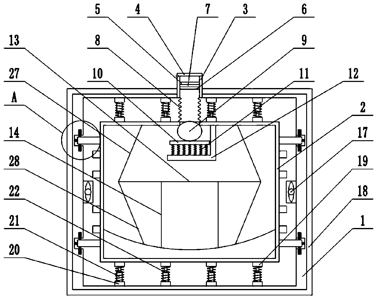
[0018] Embodiment 1 As shown in the figure, an automobile fuel tank includes an outer casing 1 and an inner casing 2 arranged inside the outer casing 1, the top and bottom of the inner casing 2 and the inner top and inner bottom of the outer casing 1 A number of first buffer devices are arranged between them, and a number of second buffer devices are arranged between the outer wall of the inner shell 2 and the inner wall of the outer shell 1. An oil injection pipe 3 is arranged in the center of the top of the outer shell 1, and the top end of the oil injection pipe 3 A cover 4 is provided, and a cylindrical sieve body is detachably provided inside the oil injection pipe 3. The cylindrical sieve body includes a first filter net 5 and a second filter net 6, and the first filter net 5 and the second filter net 6 The space is filled with a sponge layer 7, and the lower end of the oil injection pipe 3 communicates with the oil injection port provided at the top center of the inner c...

Embodiment 2

[0025] Embodiment 2 As shown in the figure, an automobile fuel tank includes an outer casing 1 and an inner casing 2 arranged inside the outer casing 1, the top and bottom of the inner casing 2 and the inner top and inner bottom of the outer casing 1 A number of first buffer devices are arranged between them, and a number of second buffer devices are arranged between the outer wall of the inner shell 2 and the inner wall of the outer shell 1. An oil injection pipe 3 is arranged in the center of the top of the outer shell 1, and the top end of the oil injection pipe 3 A cover 4 is provided, and a cylindrical sieve body is detachably provided inside the oil injection pipe 3. The cylindrical sieve body includes a first filter net 5 and a second filter net 6, and the first filter net 5 and the second filter net 6 The space is filled with a sponge layer 7, and the lower end of the oil injection pipe 3 communicates with the oil injection port provided at the top center of the inner c...


PUM


Abstract

The invention provides an automobile fuel tank. The automobile fuel tank comprises an outer shell and an inner shell. A plurality of first buffering devices are arranged between the top and the bottom of the inner shell and between the inner top and the inner bottom of the outer shell. A plurality of second buffering devices are arranged between the outer sidewall of the inner shell and the inner sidewall of the outer shell. The top center of the outer shell is provided with an oil filling pipe. A cover body is arranged at the top end of the oil filling pipe. The oil filling pipe is internally provided with a tubular screen body. The lower end of the oil filling pipe communicates with an oil filling port formed in the top center of the inner shell through a corrugated pipe. A sealing ball used for sealing the oil filling port is arranged under the oil filling port in the inner shell. The lower end of the sealing ball is provided with a supporting plate. A plurality of first springs are arranged at the lower end of the supporting plate. An L-shaped supporting plate is arranged in the position, on one side of the oil filling port, of the inner top wall of the inner shell. The lower ends of the first springs are connected with the horizontal part of the L-shaped supporting plate. The outer wall of the inner shell is provided with a plurality of cooling assemblies. The inner sidewall of the outer shell is provided with a plurality of exhaust fans. Air outlets of the exhaust fans are located outside the outer shell.

Description

technical field [0001] The invention relates to the technical field of fuel tanks, in particular to an automobile fuel tank. Background technique [0002] Automobile fuel tank is the full name of automobile fuel tank. At present, with the development of the automobile industry and the revitalization of the domestic automobile industry, the demand for automobile fuel tanks by major automobile manufacturers has shown an obvious growth trend; most of the existing automobile fuel tanks are single-layer , the vibration is too large when the car is running or when it is hit, and it is easy to damage the fuel tank; and when the car is running or shakes when it is hit, it will cause the fuel in the fuel tank to shake, causing the vehicle to make noise, and the fuel tank will also be affected by the fuel. The impact force brought by the sloshing causes problems such as the fuel tank to sway and the tank to be damaged, which poses a safety hazard. Contents of the invention [0003]...

Claims


Application Information

Patent Timeline
Patent Type & Authority Applications(China)
IPC IPC(8): B60K15/077B60K15/03
CPCB60K15/03B60K15/077B60K2015/03414B60K2015/0775B60K2015/0777
Inventor 曹学辉苏广翔高春洋
Owner TIANJIN SANXIN SUNSHINE
Why Eureka
Try Eureka