Supercharge Your Innovation With Domain-Expert AI Agents!

Capacitor lead-out cover

A technology of capacitors and cover plates, applied in the field of capacitors, can solve the problems of easy falling off of capacitor solder joints, and achieve the effect of reducing the possibility of solder joints falling off, fixing firmly and improving product quality.

Pending Publication Date: 2019-09-27
安徽纽艾新能源技术有限公司
View PDF0 Cites 0 Cited by
  • Summary
  • Abstract
  • Description
  • Claims
  • Application Information

AI Technical Summary

Problems solved by technology

[0004] A capacitor lead-out cover plate proposed by the invention solves the problem that the solder joints of the capacitor are easy to fall off

Method used


Image

  • Capacitor lead-out cover
  • Capacitor lead-out cover

Examples


Embodiment Construction

[0015] The following will clearly and completely describe the technical solutions in the embodiments of the present invention with reference to the accompanying drawings in the embodiments of the present invention. Obviously, the described embodiments are only some, not all, embodiments of the present invention.

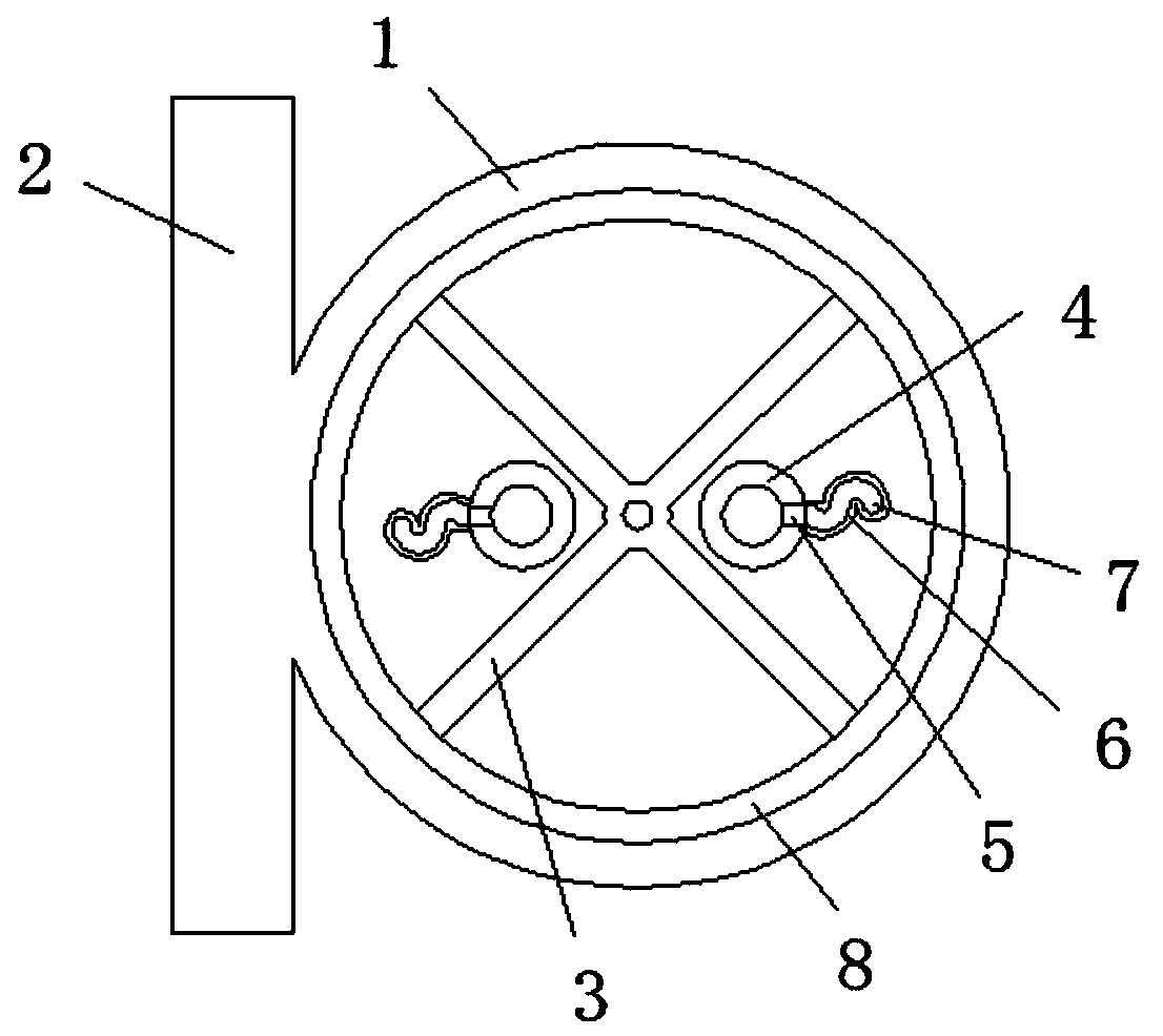
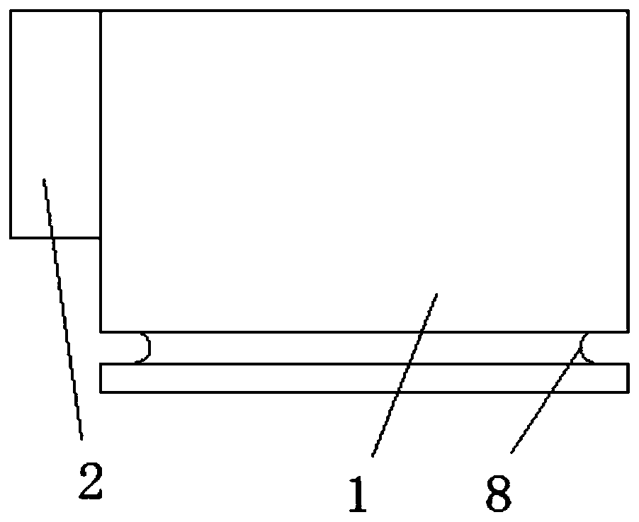
[0016] refer to Figure 1-2 , a capacitor lead-out cover plate, including a top plate 1 and a side plate 2 installed on the side wall of the top plate 1, the bottom of the top plate 1 is provided with a storage tank, the top inner wall of the storage tank is provided with a partition 3, and the two sides of the partition 3 The side is provided with the same structure and is fixed on the limit mechanism on the top inner wall of the storage tank. The limit mechanism includes a limit ring 4 and a limit plate 6 that are connected to each other. The bottom of the limit ring 4 is provided with a groove 5, and the limit The position plate 6 is arranged on one side of the gr...


PUM


Abstract

The invention belongs to the field of a capacitor, particularly relates to a capacitor lead-out cover and aims to solve a problem of easy desoldering of a capacitor in the prior art. The capacitor lead-out cover includes a top plate and a side plate mounted on a side wall of the top plate, wherein the bottom of the top plate is provided with an accommodating groove, an inner wall at the top of the accommodating groove is provided with a baffle plate, two sides of the baffle plate are provided with limit mechanisms which are identical in structure and are fixed on an inner wall of the top of the accommodating groove, the limit mechanisms include limit rings and limit plates which are mutually connected, bottoms of the limit rings are provided with grooves, the limit plates are arranged at one side of the grooves, a gap is arranged between a side wall and an outer wall of the bottom of the limit plates, the gap is internally communicated with the limit rings through the grooves, and a lead-out electrode is arranged below one end of the limit plates away from the limit rings. The capacitor lead-out cover is advantaged in that desoldering probability of the capacitor is reduced, and capacitor product quality is improved.

Description

technical field [0001] The invention relates to the field of capacitors, in particular to a capacitor lead-out cover plate. Background technique [0002] Two conductors close to each other, sandwiching a layer of non-conductive insulating medium, constitute a capacitor. A capacitor stores charge when a voltage is applied between its two plates. The capacitance of a capacitor is numerically equal to the ratio of the amount of charge on a conductive plate to the voltage between the two plates. At present, the self-healing DC support capacitors commonly used in the market are mostly circular in shape and contain two electrodes for power connection. The cover plate is assembled with a cylindrical aluminum shell. [0003] However, since the capacitor will generate heat during use, the capacitor will be slightly deformed, and the capacitor will be shaken during operation, which will cause the solder joints on the capacitor to fall off easily. In severe cases, the capacitor will...

Claims


Application Information

Patent Timeline
IPC IPC(8): H01G2/10
CPCH01G2/103
Inventor 钱加圣张寅
Owner 安徽纽艾新能源技术有限公司
Features
  • R&D
  • Intellectual Property
  • Life Sciences
  • Materials
  • Tech Scout
  • Unparalleled Data Quality
  • Higher Quality Content
  • 60% Fewer Hallucinations
Learn More