Stable lock bolt

A kind of anti-loosening bolt and stable technology, applied in the direction of bolts, screws, nuts, etc., can solve the problems of troublesome installation process and inability to disassemble, and achieve the effect of good anti-loosening effect and convenient use.

Active Publication Date: 2019-10-15
江苏甬怡紧固件有限公司
View PDF8 Cites 12 Cited by
  • Summary
  • Abstract
  • Description
  • Claims
  • Application Information

AI Technical Summary

Problems solved by technology

However, it needs to change the threaded hole structure of the connected parts, which is not suitable for most occasions. At the same time, it is directly locked after installation and cannot be disassembled. It is also not suitable for occasions that require disassembly and maintenance, and its installation process is also very troublesome.

Method used


Image

  • Stable lock bolt
  • Stable lock bolt
  • Stable lock bolt

Examples


Embodiment Construction

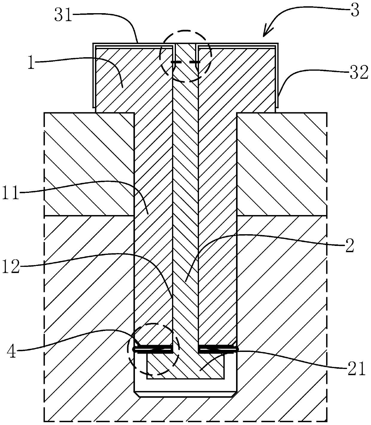
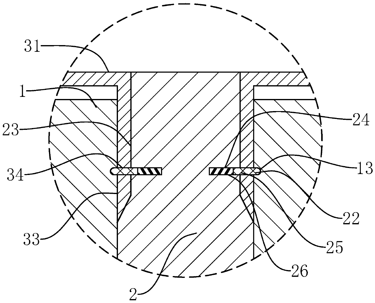
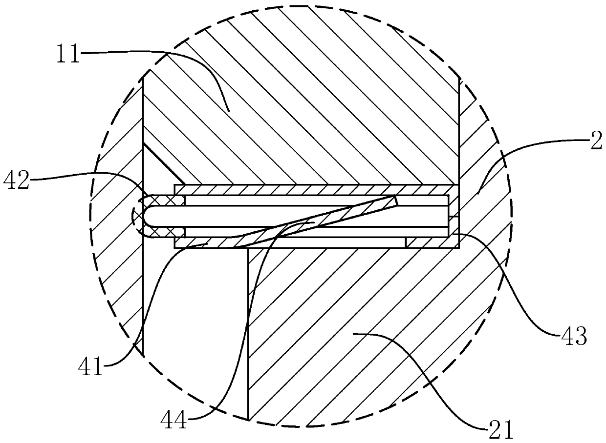
[0036] The following are specific embodiments of the present invention and in conjunction with the accompanying drawings, the technical solutions of the present invention are further described, but the present invention is not limited to these embodiments.

[0037]like Figure 1-9 As shown, a stable anti-loosening bolt of the present invention includes a bolt head 1 and an externally threaded bolt shank 11 whose top end is fixed on the bolt head 1. The bolt head 1 is in the shape of a round head, and the bolt head 1 and the bolt shank 11 are coaxial It is provided with a rod-shaped pressure hole 12, and also includes a round rod-shaped pressure rod 2 movably fitted in the pressure hole 12, and also includes an adjustment cap 3. The adjustment cap 3 includes an adjustment plate 31 fixed to the top of the pressure rod 2 and the inner wall of the top end. The sleeve-shaped adjustment sleeve 32 fixed to the outer edge of the adjustment plate 31, the inner wall of the adjustment sl...


PUM


Abstract

The invention provides a stable lock bolt, and belongs to the field of mechanical fasteners. The stable lock bolt solves the problem that an existing bolt is poor in loosening preventing effect. The stable lock bolt comprises a bolt head and a bolt rod, wherein the bolt head is in a round head shape, and a pressing hole is formed in the bolt head and the bolt rod. A pressing rod penetrating through the pressing hole is further included. An adjusting cap is further included and comprises an adjusting plate fixed to the top end of the pressing rod and an adjusting sleeve fixed to the outer edgeof the adjusting plate, wherein the adjusting sleeve sleeves the bolt head, and a pressing block is fixed to the bottom end of the pressing rod. An expansion gasket sleeving the pressing rod is further included. The hole wall of the pressing hole is provided with a limiting groove. The rod wall of the pressing rod is provided with a limiting block which is located in the limiting groove in a sliding manner. The distance between the middle portion of the limiting groove and the top end of the pressing hole is smaller than the distance between the two ends of the limiting groove and the bottom end of the pressing hole, the distance between the front end of the limiting groove and the top end of the pressing hole is larger than the distance between the rear end of the limiting groove and thetop end of the pressing hole, smooth transition is achieved from the middle portion of the limiting groove to the two ends of the limiting groove, and an elastic reset mechanism is arranged between the pressing rod and the bolt rod. The bolt is better in loosening preventing effect.

Description

technical field [0001] The invention belongs to the technical field of mechanical fasteners and relates to a stable anti-loosening bolt. Background technique [0002] The vibration of mechanical equipment will cause the bolts to fall off, which will affect the normal operation of the equipment and seriously affect the safety and stability of the equipment. In order to improve the anti-loosening performance of bolts, gaskets will be added between the bolts and the connected parts, and the bolts will be tightened with high strength at the same time. The purpose is to improve the friction between the external thread and the internal thread. The threads will still gradually loosen, and the high-strength tightening of the bolts will easily lead to slight deformation of the surface of the connected parts. At the same time, due to the different tightening strength of each bolt, the degree of deformation of each part of the surface of the connected parts is also different, and it wi...

Claims


Application Information

Patent Timeline
Patent Type & Authority Applications(China)
IPC IPC(8): F16B39/22F16B35/00
CPCF16B35/00F16B39/22
Inventor 张丽丽
Owner 江苏甬怡紧固件有限公司
Why Eureka
Try Eureka