Side plate hinge structure and large container

A large container and side plate technology, applied in the field of side plate hinge structure and large container, can solve the problems of inconvenient installation and disassembly, achieve the effect of convenient rotation, lighten labor intensity and reduce resistance

Inactive Publication Date: 2019-10-22
SHANGHAI XINYIDA PLASTIC PALLET +1
View PDF6 Cites 0 Cited by
  • Summary
  • Abstract
  • Description
  • Claims
  • Application Information

AI Technical Summary

Problems solved by technology

[0006] Aiming at the technical problem of inconvenient installation and disassembly of the side panel hinge structure proposed in the background technology, the first purpose of the present invention is to provide a side panel hinge structure. By setting the rotation head and the limit rotation head, when installing, the rotation head is from The position of the installation port is installed in the installation groove, and the first semicircular groove is movably sleeved on the rotating column. At the same time, the second semicircular groove on the limit rotating head is movably sleeved on the limit rotating column. The direction of the notch of the first semi-circular groove is misaligned or set oppositely, which can prevent the side plate from falling off, and at the same time, the side plate can be installed directly downward from the vertical direction to achieve the purpose of reducing the labor intensity of the operator

Method used


Image

  • Side plate hinge structure and large container
  • Side plate hinge structure and large container
  • Side plate hinge structure and large container

Examples


Embodiment Construction

[0039] The present invention will be further described in detail below in conjunction with the embodiments and the accompanying drawings, but the embodiments of the present invention are not limited thereto.

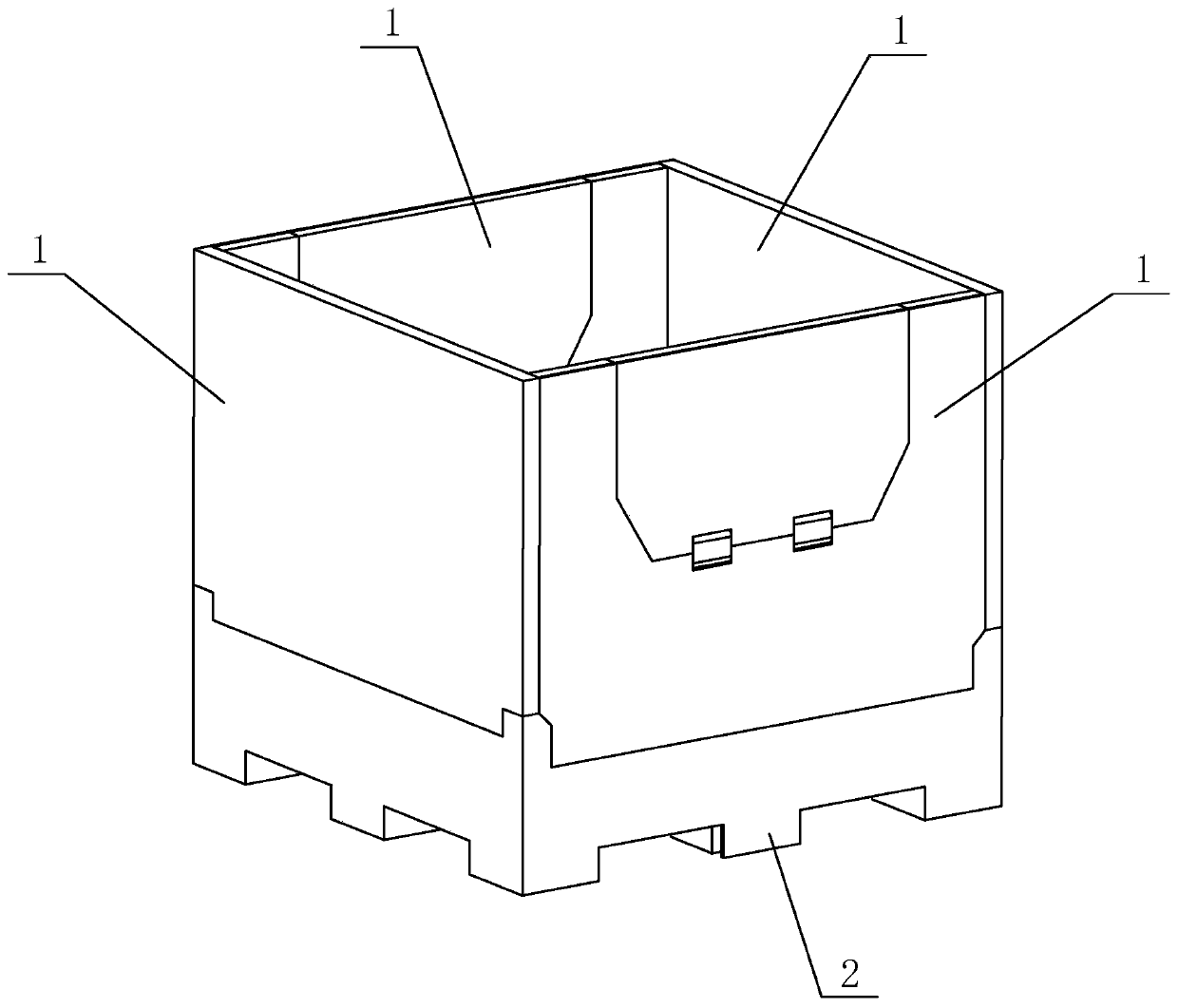
[0040] A large container, combined with figure 2 It can be seen that in this implementation, the large-scale container is disclosed by using a plastic folding box. The folding box includes four side panels 1 and a base 2, and the four side panels 1 are all rotatably mounted on the base 2, so that the side panels 1 can be folded and folded conveniently. It is stored on the base 2, and the empty plastic folding box is stored. In order to facilitate the rotational installation of the side plate 1 on the base 2 , a side plate hinge structure is provided between the side plate 1 and the base 2 .

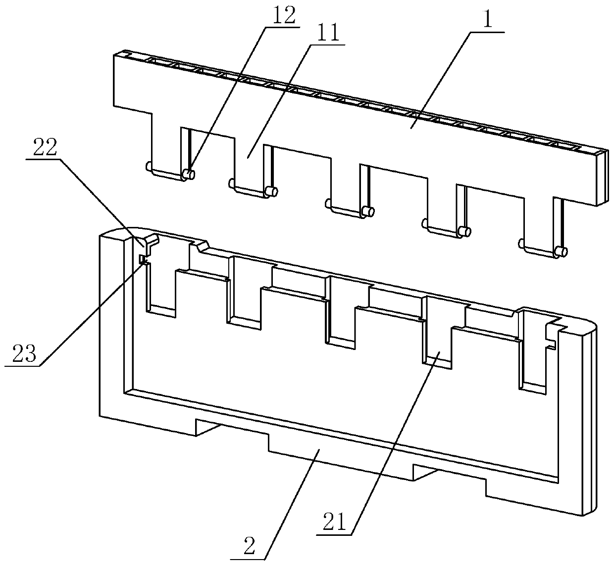
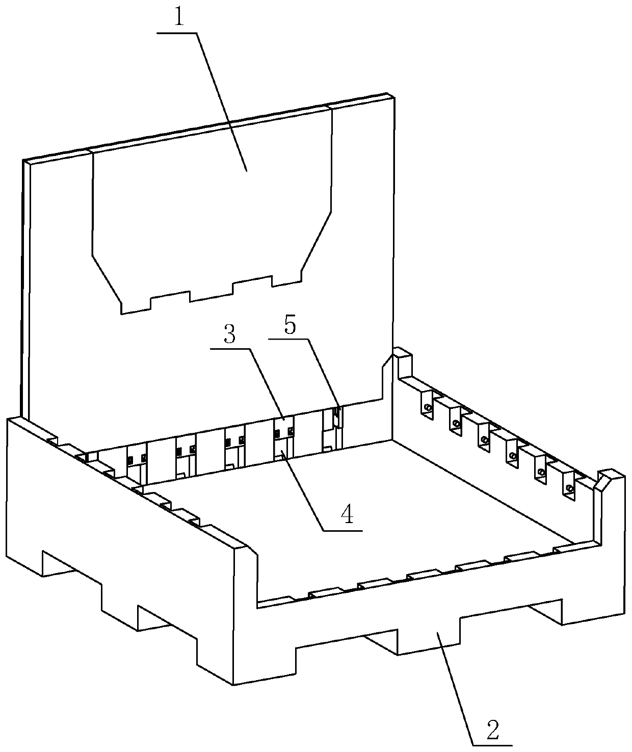
[0041] Specifically, combine image 3 and Figure 4It can be seen that the hinged structure of the side plate includes the above-mentioned side plate 1 and the above-mentioned b...


PUM


Abstract

The invention relates to the technical field of hinge connecting structures, and discloses a side plate hinge structure and a large container.The technical problem that an existing side plate hingingstructure is inconvenient to mount and dismount is solved, the side plate hinging structure comprises side plate bodies and a base, wherein rotating heads are arranged on the side edges of the side plate bodies, mounting groovesareformed in the base, first semicircular groovesareformed in the rotating heads, rotating columns are arranged on the two side walls of the mounting grooves, mounting portsareformed between the rotating columns and the side walls of the mounting grooves, the first semicircular groovesare arranged in the mounting grooves from the positions of the mounting ports, and thefirst semicircular groovesaremovably arranged on the rotating columns in a sleeve mode; limiting rotating heads are arranged at the position between the plurality of rotating heads or at the two sides, second semicircular groovesareformed in the limiting rotating heads, and the groove opening directions of the second semicircular grooves and the groove opening directions of the first semicirculargrooves are staggered or opposite, limiting rotating columns are arranged in the mounting grooves, and the second semicircular grooves are movably arrangedon the limiting rotating columns in a sleevemode. According to the technical scheme, the side plate bodies can be directly mounted downwards from the vertical direction, so that the purpose of reducing the labor intensity of operators is achieved.

Description

technical field [0001] The invention relates to the technical field of hinge connection structures, more specifically, it relates to a side plate hinge structure and a large container. Background technique [0002] At present, it is very common to use containers to carry or transport various materials, and these containers also have a series of specifications from large to small. For the convenience and quickness of production turnover or transportation and cost savings, plastic containers have also begun to be widely used. Large containers of this type have a base and four side walls, and the side walls are integrated or foldable. When the volume of the container is large, it is often necessary to have an openable door on one or more side panels to facilitate access to the bottom of the container or to install and remove some additional components at the bottom. [0003] At the same time, in order to store empty containers, reduce the storage area of ​​empty containers, an...

Claims


Application Information

Patent Timeline
Patent Type & Authority Applications(China)
IPC IPC(8): B65D90/00B65D90/02
CPCB65D90/00B65D90/02
Inventor 胡文龙
Owner SHANGHAI XINYIDA PLASTIC PALLET
Why Eureka
Try Eureka