A reversible yarn textile operation guide tensioning device and method

A tensioning device and yarn technology, applied in the direction of transportation and packaging, thin material handling, conveying filamentous materials, etc., can solve the problems of reducing yarn strength, yarn outer surface wear, yarn knotting, etc. Achieve the effect of reducing the degree of wear, shortening the winding length and reducing friction

Active Publication Date: 2020-03-27
福建石狮晨光化纤染织有限公司
View PDF5 Cites 0 Cited by
  • Summary
  • Abstract
  • Description
  • Claims
  • Application Information

AI Technical Summary

Problems solved by technology

[0003] (1) When the textile machine pulls the yarn, the speed of the yarn drum is uncontrollable. When the yarn is stopped, the yarn drum still rotates at a certain angle through inertia to make the yarn in a slack state, resulting in a suspended The yarns are intertwined, and when the yarns are pulled and transported again, the intertwined yarns are prone to knotting, and the yarns are likely to be pulled to breakage due to sudden changes in tension when pulling the yarns;
[0004] (2) During the yarn conveying process, there may be a direction-changing conveying situation. The existing yarn conveying is usually passively changing the direction, and the friction between the yarn and the yarn bobbin changing position is relatively large, causing the yarn to be out of the direction. The surface is worn, which reduces the strength of the yarn and makes it easier to break than normal yarn, which seriously affects the production quality of the yarn

Method used


Image

  • A reversible yarn textile operation guide tensioning device and method
  • A reversible yarn textile operation guide tensioning device and method
  • A reversible yarn textile operation guide tensioning device and method

Examples


Embodiment Construction

[0035] Embodiments of the present invention will be described below with reference to the drawings. During this process, in order to ensure the clarity and convenience of the description, we may exaggerate the width of the lines or the size of the constituent elements in the diagram.

[0036] In addition, the following terms are defined based on the functions in the present invention, and may be different according to the user's or operator's intention or practice. Therefore, these terms are defined based on the entire content of this specification.

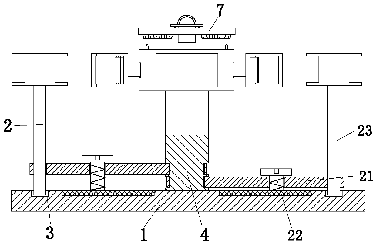
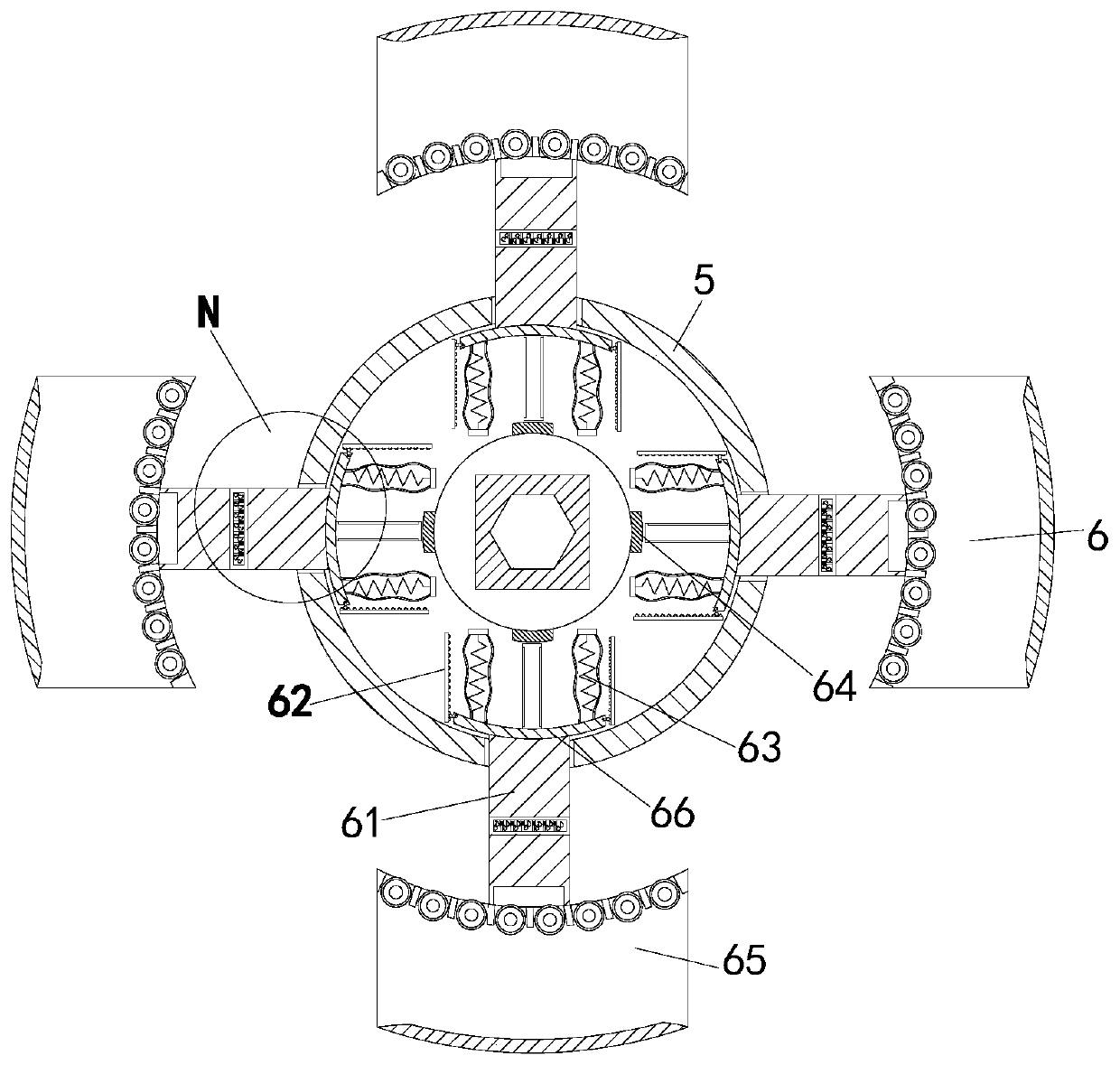
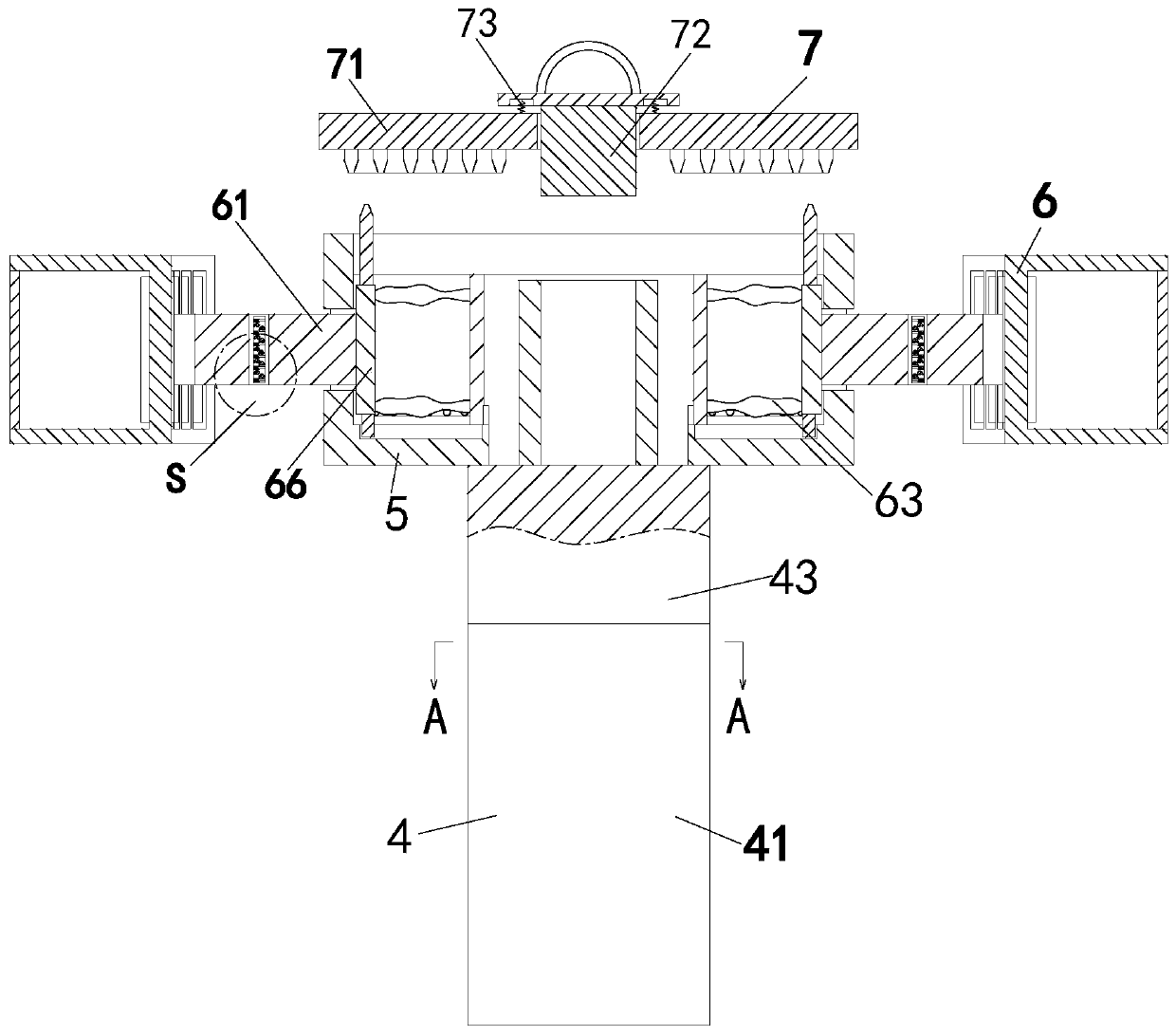
[0037] Such as Figure 1 to Figure 7 As shown, a direction-changing yarn textile operation guiding tensioning device includes a bottom plate 1, two direction-changing pulley rods 2, an annular chute 3, a connecting column 4, a connecting plate 5, an anti-loosening device 6 and a rotating plate 7. There is an annular chute 3 on the base plate 1, and the annular chute 3 is connected to the two direction changing pulley rods 2 thr...


PUM


Abstract

The invention relates to a direction changing type yarn textile working guide tensioning device and method. A bottom plate, direction changing pulley rods, an annular sliding groove, a connecting column, a connecting disc, anti-loosening devices and a rotating disc are included; the bottom plate is provided with the annular sliding groove, the annular sliding groove is connected with the directionchanging pulley rods in a sliding fit manner, the connecting column is installed in the middle portion of the bottom plate, the connecting column is located between the two direction changing pulleyrods, the upper end of the connecting column is provided with the connecting disc, the anti-loosening devices are evenly formed in the connecting disc in the circumferential direction, and the upper end of the connecting disc is provided with the rotating disc. According to the direction changing type yarn textile working guide tensioning device and method, yarns are synchronously supported to beopen through the anti-loosening devices, the winding length of the yarns is changed, and the yarns are wholly in the tightening state; and the conveying direction of the yarns is changed by position adjustment of the two direction changing pulley rods, friction generated when the yarns are subjected to direction-changing conveying, and the abrasion degree of the yarns is reduced.

Description

technical field [0001] The invention relates to the field of textile machinery, in particular to a reversible yarn weaving operation guiding and tensioning device and method. Background technique [0002] In the textile industry, the yarn is wound on the yarn bobbin, and the yarn bobbin is arranged on the yarn frame, and the yarn bobbin is continuously rotated on the yarn frame, so that the textile machine can carry out the weaving operation. When the textile machine needs to pull and transport the yarn, the following problems exist in the actual work process: [0003] (1) When the textile machine pulls the yarn, the speed of the yarn drum is uncontrollable. When the yarn is stopped, the yarn drum still rotates at a certain angle through inertia to make the yarn in a slack state, resulting in a suspended The yarns are intertwined, and when the yarns are pulled and transported again, the intertwined yarns are prone to knotting, and the yarns are likely to be pulled to breaka...

Claims


Application Information

Patent Timeline
Patent Type & Authority Patents(China)
IPC IPC(8): B65H57/14B65H59/06B65H59/36
CPCB65H57/14B65H59/06B65H59/36B65H2701/31
Inventor 杜秀兰李玮
Owner 福建石狮晨光化纤染织有限公司
Why Eureka
Try Eureka