
Improved Wheel Track Reduction for Robotic Lawn Mowers

A technology of lawn mowers and robots, applied to agricultural machinery and implements, instruments, applications, etc., to reduce risks, maintain robustness and safety, and reduce the risk of misoperation

Active Publication Date: 2022-04-12
HUSQVARNA AB
View PDF20 Cites 0 Cited by
  • Summary
  • Abstract
  • Description
  • Claims
  • Application Information

AI Technical Summary

Problems solved by technology

Since robotic lawnmowers must be recharged repeatedly, there is a risk of wheel tracks forming along such cables

Method used


Image

  • Improved Wheel Track Reduction for Robotic Lawn Mowers
  • Improved Wheel Track Reduction for Robotic Lawn Mowers
  • Improved Wheel Track Reduction for Robotic Lawn Mowers

Examples


Embodiment Construction

[0023] The disclosed embodiments will be described more fully hereinafter with reference to the accompanying drawings, in which certain embodiments of the invention are shown. However, the invention may be embodied in many different forms and should not be construed as limited to the embodiments set forth herein; rather, these embodiments are provided by way of example so that this disclosure will be thorough and complete, and will convey to the Those skilled in the art fully convey the scope of the present invention. Throughout the text, like reference numerals refer to like elements

[0024] It should be noted that all indications of rotational speed, duration, workload, battery level, operating level, etc. are given as examples and may be varied in many different ways that will be apparent to those skilled in the art. These changes can be for individual entities as well as groups of entities, and can be absolute or relative.

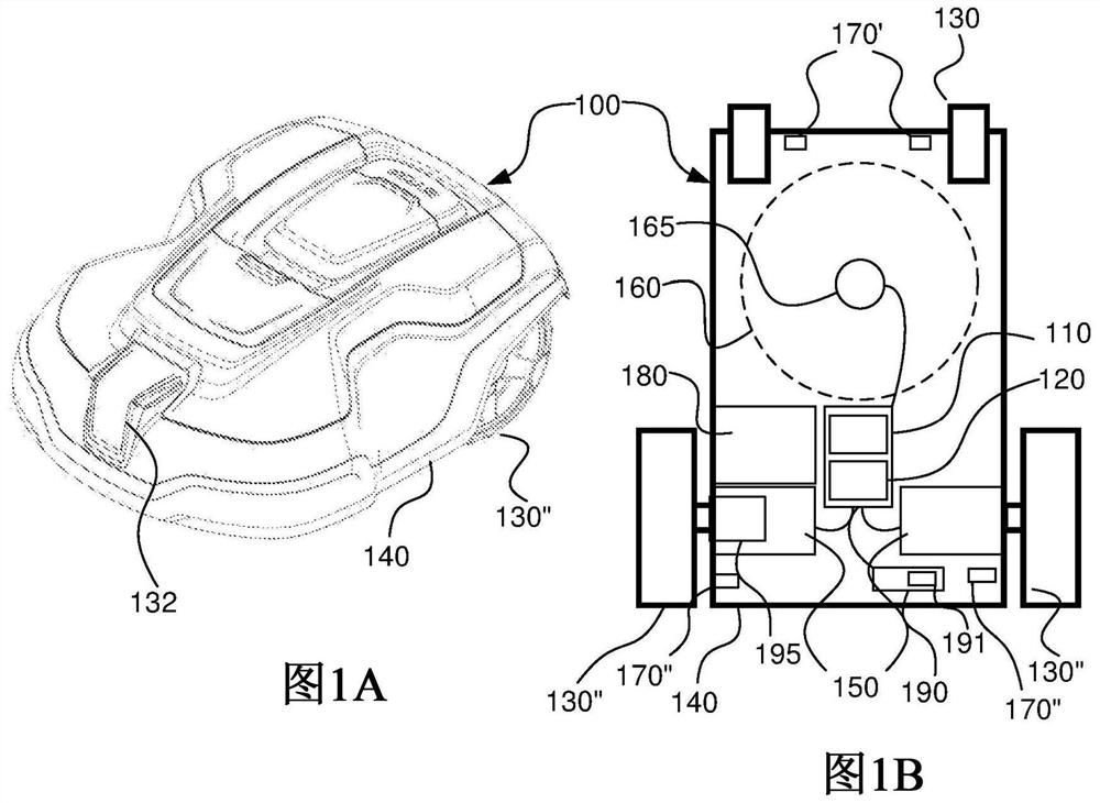
[0025] Figure 1A Illustrated is a perspectiv...


PUM


Abstract

A robotic lawnmower system comprising a robotic lawnmower (100) and a signal generator (240) to which cables (250, 260) are connected, the signal generator (240) being configured as Signals (245) are transmitted through the cables (250, 260). The robotic lawn mower (100) includes a sensor (170) configured to pick up the magnetic field generated by the signal (245) in the cable (250, 260), thereby receiving the signal (245). The controller (110) is configured to follow the cable (250, 250, 260).

Description

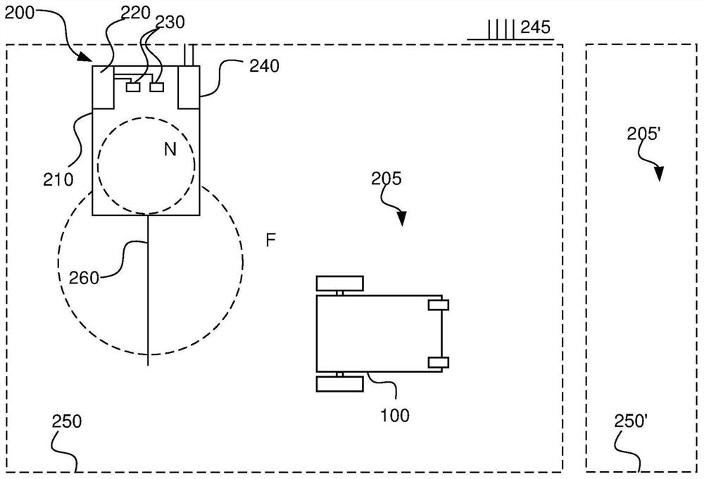
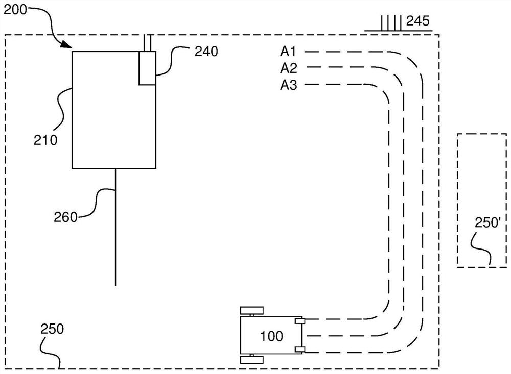
technical field [0001] The present application relates to robotic lawnmowers, and more particularly to systems and methods for performing improved wheel-track reduction in work areas. Background technique [0002] Autonomous or robotic power tools such as robotic lawn mowers are becoming more and more popular. In a typical configuration, a work area such as a garden is surrounded by a boundary cable, the purpose of which is to keep the robotic lawnmower within the work area. Robotic lawnmowers are often configured to follow boundary lines or guide cables as they search for their charging stations. Since robotic lawnmowers must be recharged repeatedly, there is a risk of wheel tracks forming along such cables. It should be understood here that the wheel track includes not only the actual track made by the wheels, but also the area under the robotic mower as it moves along the cable which will be cut more often than the rest of the work area , thus forming more or less diff...

Claims


Application Information

Patent Timeline
Patent Type & Authority Patents(China)
IPC IPC(8): A01D34/00G05D1/00
CPCG05D1/0265A01D34/008G05D1/244G05D1/648A01D34/64
Inventor 马库斯·利耶达尔
Owner HUSQVARNA AB
Learn More