
SIM card support ejecting device and terminal

A technology of pop-up device and card tray, which is applied in the direction of telephone structure, telephone communication, electrical components, etc., can solve the problems of unsatisfactory convenience, users will not carry it with them, poor user experience, etc.

Inactive Publication Date: 2019-11-01
NUBIA TECHNOLOGY CO LTD
View PDF6 Cites 4 Cited by
  • Summary
  • Abstract
  • Description
  • Claims
  • Application Information

AI Technical Summary

Problems solved by technology

[0005] The main purpose of the present invention is to propose a SIM card tray pop-up device and terminal, which aims to solve the problem that in the prior art, a card pin is needed when taking out the SIM card and installing the SIM card, and the user does not carry the card pin with him. It brings great inconvenience to users, cannot meet the needs of convenience, and has poor user experience

Method used


Image

  • SIM card support ejecting device and terminal
  • SIM card support ejecting device and terminal
  • SIM card support ejecting device and terminal

Examples


no. 1 example

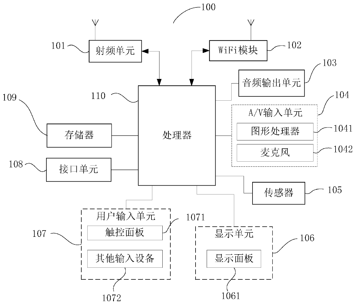
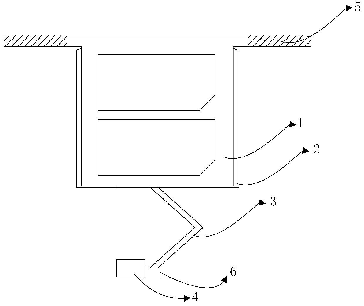
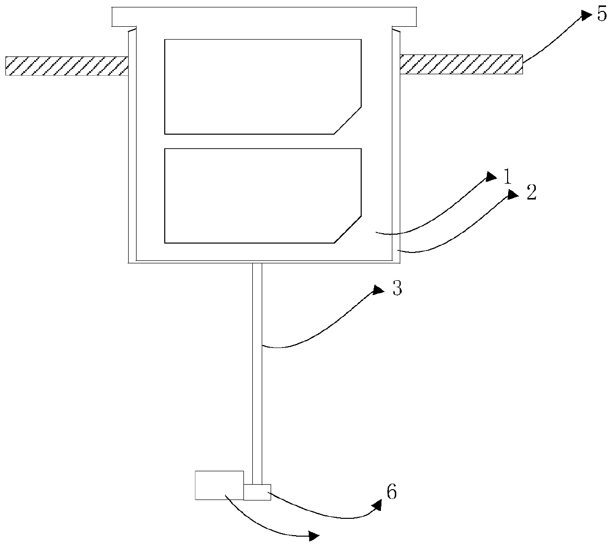
[0049] In order to solve the problem in the prior art, when taking out the SIM card and installing the SIM card, the card needle is required, and the user does not carry the card needle with him, which brings great inconvenience to the user, cannot meet the needs of convenience, and improves the user experience. Poor problem, present embodiment will provide a kind of SIM card holder pop-up device, refer to Figure 2 to Figure 5 , Figure 2 to Figure 5 The schematic diagram of the SIM card tray ejecting device provided for this embodiment, the SIM card tray ejecting device includes:

[0050] A card tray 1 for placing a SIM card, a card holder 2 for accommodating the card tray 1, a memory metal bracket 3, and a heating device 4;

[0051] The heating device 4 is next to the memory metal support 3. When the heating device 4 heats the temperature to the preset temperature threshold, the memory metal support 3 deforms from the first state to the second state. When the memory metal ...

no. 2 example

[0073] This embodiment is based on the first embodiment, taking a more specific structure as an example to further illustrate the present invention.

[0074] The present embodiment includes the following structures with the mobile phone for illustration, and the mobile phone includes a SIM card, a card holder 1 for placing the SIM card, a card holder 2 for accommodating the card holder 1, a memory metal support 3, and a heating device 4; see figure 2 , the heating device 4 is close to the memory metal bracket 3, and the memory metal bracket 3 is placed under the card tray 1, one end of the memory metal bracket 3 is fixed on the bracket fixed end 6 on the mobile phone shell 5, and the other end is against the card tray 1 bottom. And when the Cato 1 is not ejected, the part of the Cato 1 visible to the user is closed and unopened, and the top end of the Cato 1 is provided with a circle of waterproof silicone ring, which is located between the Cato 1 and the mobile phone case. ...


PUM


Abstract

The invention provides an SIM card support ejecting device. The SIM card support ejecting device comprises a card support for placing an SIM card, a card seat for accommodating the card support, a memory metal bracket and a heating device. The heating device is close to the memory metal support. When the heating device heats the temperature to a preset temperature threshold value, the memory metalsupport deforms from a first state to a second state, and when the memory metal support is in the first state, the card support is located in the terminal shell, and when the memory metal support isin the second state, the card support pops up from the terminal shell. The invention further provides a terminal. Through the above scheme, when the SIM card needs to be taken out from the terminal orthe SIM card needs to be installed, the temperature is heated to the preset temperature threshold value through the heating device, so that the memory metal support deforms, the card support is driven to pop out of the terminal shell, automatic ejection of the SIM card support is achieved, the SIM card is convenient to take out or install, the use convenience is improved, and the user experienceis improved.

Description

technical field [0001] The present invention relates to the technical field of terminals, and more specifically, to a device for ejecting a SIM card tray and a terminal. Background technique [0002] With the large-scale popularization of terminals such as smart phones and tablet computers, users use terminals more and more frequently. In recent years, users have put forward higher and higher requirements for terminal use experience. [0003] At present, the design of the mobile phone SIM card tray is mainly the way that the card tray is matched with the card holder. The card needle is required when taking out the SIM card and installing the SIM card. Users do not carry the card needle with them in daily use, but need to take it out temporarily It is difficult to find other objects to replace the card pin when installing the SIM card or the SIM card, which brings great inconvenience to the user, cannot meet the needs of convenience, and has poor user experience. [0004] Th...

Claims


Application Information

Patent Timeline
Patent Type & Authority Applications(China)
IPC IPC(8): H04B1/3818H04M1/02
CPCH04B1/3818H04M1/0274
Inventor 代梦婉
Owner NUBIA TECHNOLOGY CO LTD
Learn More