Magnet steel sticking device for permanent magnet motor rotor

A technology of permanent magnet motors and magnets, which is applied in electromechanical devices, manufacturing motor generators, manufacturing stator/rotor bodies, etc., and can solve problems such as complex operation procedures, no automatic placement of magnets, and low work efficiency

Pending Publication Date: 2019-11-05
浙江佳雪微特电机有限公司
View PDF0 Cites 0 Cited by
  • Summary
  • Abstract
  • Description
  • Claims
  • Application Information

AI Technical Summary

Problems solved by technology

There are two main methods for pasting permanent magnets of outer rotor motors. One is to put the outer rotor to be pasted with permanent magnets into an injection mold for injection molding to obtain an outer rotor with plastic-encapsulated permanent magnets. The operation process is not only complicated, but also the cost of pasting is too expensive
[0003] At present, the existing permanent magnet motor rotor magnet sticking device does not have a device for automatically inserting magnets, resulting in low work efficiency

Method used


Image

  • Magnet steel sticking device for permanent magnet motor rotor
  • Magnet steel sticking device for permanent magnet motor rotor
  • Magnet steel sticking device for permanent magnet motor rotor

Examples


Embodiment Construction

[0027] In order to make the object, technical solution and advantages of the present invention clearer, the present invention will be further described in detail below in conjunction with the accompanying drawings and embodiments. It should be understood that the specific embodiments described here are only used to explain the present invention, not to limit the present invention.

[0028] In describing the present invention, it should be understood that the terms "length", "width", "upper", "lower", "front", "rear", "left", "right", "vertical", The orientation or positional relationship indicated by "horizontal", "top", "bottom", "inner", "outer", etc. are based on the orientation or positional relationship shown in the drawings, and are only for the convenience of describing the present invention and simplifying the description, rather than Nothing indicating or implying that a referenced device or element must have a particular orientation, be constructed, and operate in a ...


PUM


Abstract

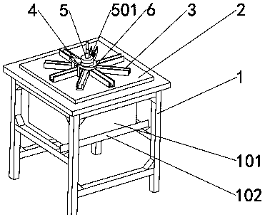
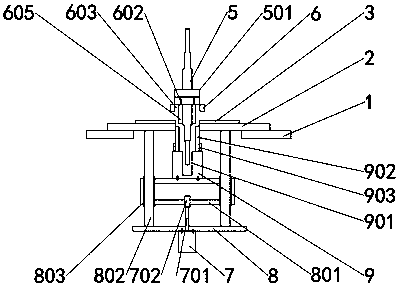
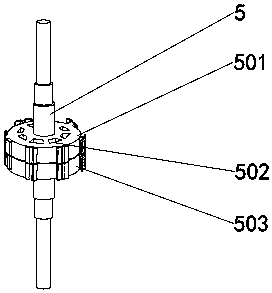
The invention belongs to the technical field of motors and particularly relates to a magnet steel sticking device for a permanent magnet motor rotor. The device comprises a device body, an upper end surface of the device body is fixedly connected with an operation table, an operation box is set in the device body, a cylinder is arranged inside the operation box, an output end of the cylinder is equipped with a telescopic rod, an upper end of the telescopic rod is fixedly connected to a cylinder connecting head, an outer side wall of the cylinder connecting head is fixedly connected to a pushing block, an upper end surface of the pushing block is fixedly connected to a pushing pin fixing block, an upper end surface of the pushing pin fixing block is provided with a core groove, and the upper end surface of the pushing pin fixing block is fixedly connected to a plurality of pushing pins matched with magnetic steel holes. Magnetic steels are pushed to a lower side of an upper guide blockthrough magnetic steel grooves, then the cylinder is operated to drive the telescopic rod to move upwards, thus, the pushing pin fixing block and the pushing pins are driven to move upward when the pushing block is allowed to move upwards, then the pushing pins push the magnetic steels to pass through the magnetic steel holes upwards to be inserted into the magnetic steel grooves, and therefore, the magnetic steels can be automatically inserted into the magnetic steel grooves by the device.

Description

technical field [0001] The invention relates to the technical field of motors, in particular to a permanent magnet motor rotor magnet sticking device. Background technique [0002] The outer rotor motor includes an outer rotor and an inner stator. The inner stator is placed in the outer rotor. The outer rotor includes an outer rotor shell and a back yoke. The back yoke is located on the inner wall of the outer rotor shell. permanent magnet. In the prior art, how to achieve low paste cost, simple and convenient process, short paste cycle, and meet the paste precision requirements of the external rotor permanent magnet paste process has always been the pursuit of manufacturers in this field. There are two main methods for pasting permanent magnets of outer rotor motors. One is to put the outer rotor to be pasted with permanent magnets into an injection mold for injection molding to obtain an outer rotor with plastic-encapsulated permanent magnets. The operation process is no...

Claims


Application Information

Patent Timeline
Patent Type & Authority Applications(China)
IPC IPC(8): H02K15/03
CPCH02K15/03
Inventor 周延峰钮建华柏晓华戴旭良闵月峰
Owner 浙江佳雪微特电机有限公司
Why Eureka
Try Eureka