Plug-in device for sandwishing material between layers

A technology for inserting devices and sheet layers, which is applied in the directions of transportation and packaging, delivery of filamentous materials, and installation of optical fibers/cables, etc. It can solve the problems of cost increase, occlusion, and efficiency reduction, and achieve the effect of reducing costs and labor costs

Inactive Publication Date: 2005-10-05
UBE NITTO KASEI CO LTD
View PDF0 Cites 0 Cited by
  • Summary
  • Abstract
  • Description
  • Claims
  • Application Information

AI Technical Summary

Problems solved by technology

[0010] With the traditional interlayer inserting method, there will be a gap of more than half the diameter of the winding separator between each final winding layer and the flange of the winder, which makes it difficult to mount on the upper layer , easy to fall and cause bite phenomenon
[0011] The following problems arise here: starting from the 5th round of the final winding, it is necessary to pay attention to the problem of poor winding or embedding. Material insertion, so it takes a lot of time and labor costs
[0012] On the other hand, although the method of winding the ribbon on the support body to prevent the grooves from being engaged has been proposed, it is necessary to increase the bonding and detachment equipment of the ribbon, and the process is increased and the efficiency is reduced, so the cost is also greatly reduced. Increase

Method used


Image

  • Plug-in device for sandwishing material between layers
  • Plug-in device for sandwishing material between layers
  • Plug-in device for sandwishing material between layers

Examples


Embodiment Construction

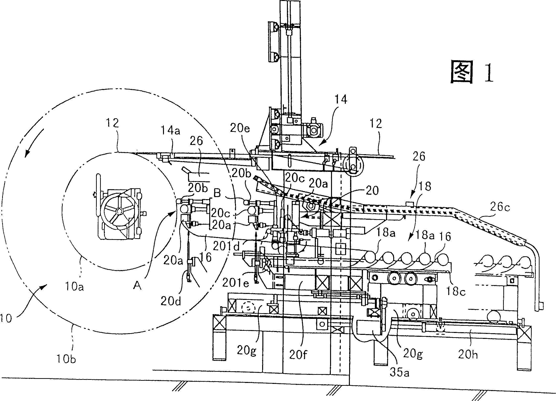
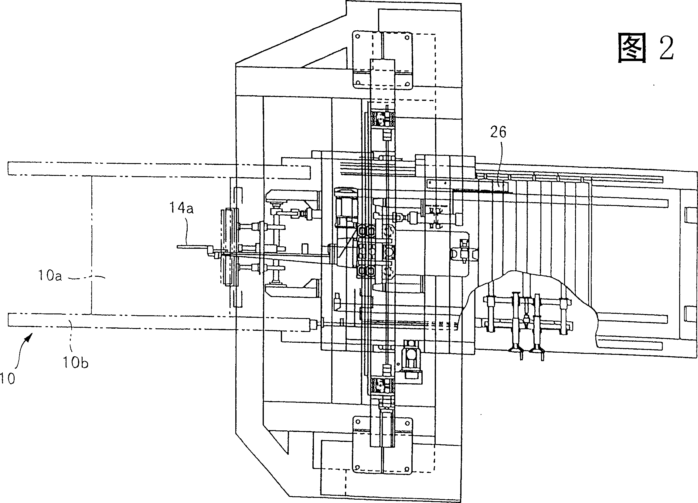
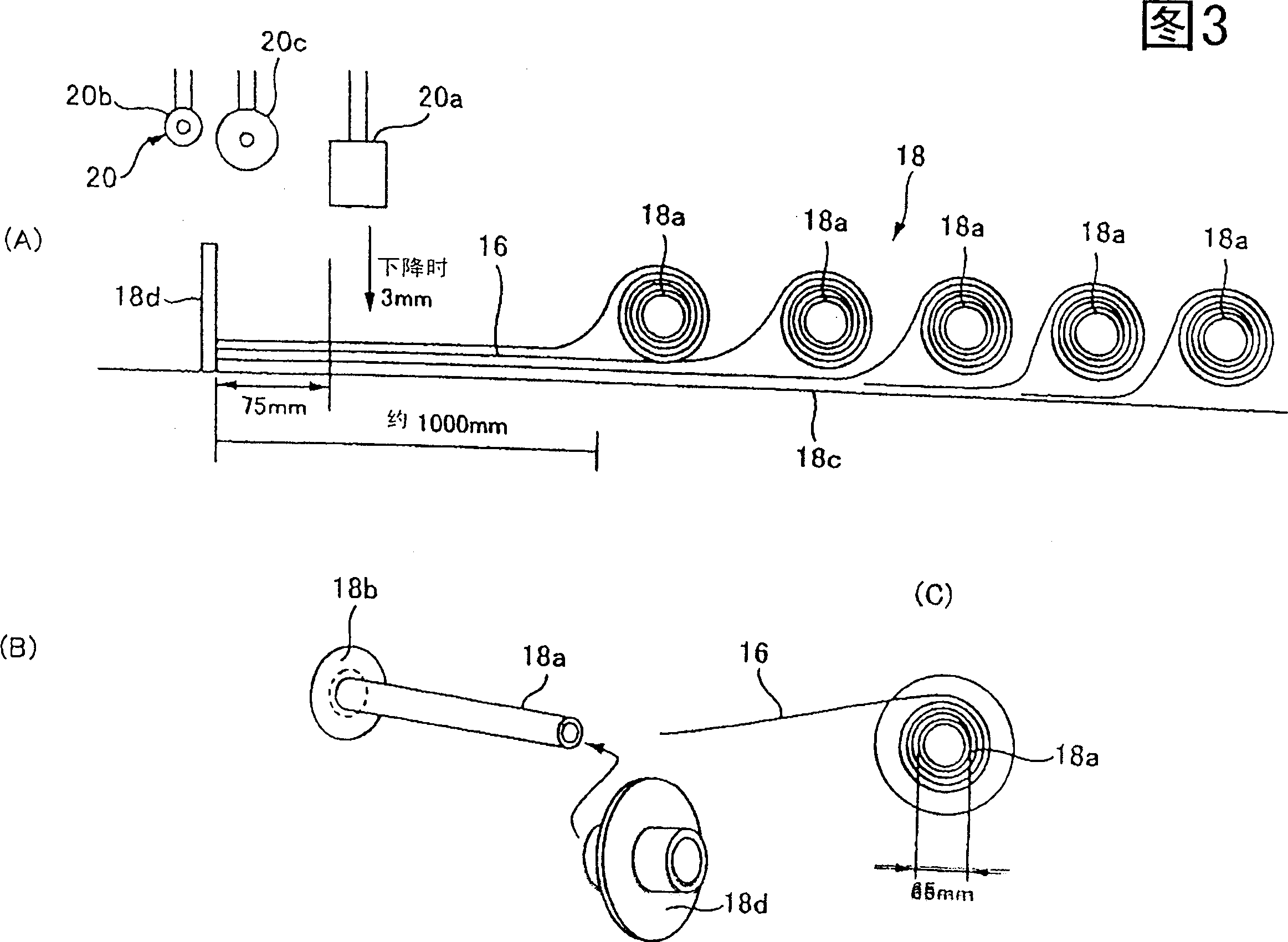
[0047] Hereinafter, the applicable embodiments of the present invention will be described in detail with reference to the drawings. 1 to 3 show Embodiment 1 of an interlayer inserting device related to the present invention.

[0048] The interlayer inserting device shown in the figure is used when the separator for the optical cable is wound in multiple layers around the outer circumference of a bobbin 10 driven by a traversing mechanism 14 .

[0049] The winder 10 has a cylindrical reel 10a and flanges 10b arranged in pairs at both ends of the reel 10a. The reel 10a is supported approximately horizontally and rotates in the direction indicated by the arrow in FIG. 1 , and its exterior is neatly wound There are multiple layers of separator 12 .

[0050] Plate-shaped interlayer materials 16 such as kraft paper or cardboard are sandwiched between upper and lower layers of the wound separator 12 . The traverse mechanism 14 is, for example, basically the same structure as that s...


PUM


Abstract

The invention provides an interlayer material capable of automatically inserting in the interlayer material. This interlayer material insertion device inserts a sheet-typed interlayer material 16 between upper and lower layers of a spacer 12 when the spacer 12 is, in a multi-layer manner, wound around the outer periphery of a rotationally driven bobbin 10 through a traverse mechanism 14. This device is equipped with a winding mechanism 20 which sucks and retains the end of a piece of interlayer material 18 from a stock 18 of the interlayer material 16, presses the interlayer material 16 against a winding spacer and rotates it with the bobbin 10 before the spacer 12 guided by the traverse mechanism 14 runs over the lower winding spacer, and inserts the end of the interlayer material 16 therebetween immediately before the spacer 12 runs over the lower winding spacer, and a winding auxiliary mechanism 26 which controls the turn-up of the interlayer material wound around the winding spacer from the above as bobbin rotates after the winding mechanism 20 releases a condition where the interlayer material is pressed against the winding spacer.

Description

technical field [0001] The present invention relates to an insertion device for inserting an interlayer interlayer when winding a separator for an optical cable. Background technique [0002] Conventionally, the fiber optic cable formed of polyethylene (PE) as the main material is press-molded with a spacer, and then passed through the winding process of the reel formed by the flanges fixed to the cylindrical reel and both ends. , The above-mentioned wound separator is supplied to the optical cable manufacturing process. In the assembly process of optical cable manufacturing, the optical cables are respectively loaded into several grooves of the separator. [0003] In the winding process of the above-mentioned winder, when the separators cross each other, the ribs are prone to deformation, and this deformation will cause abnormalities in the optical cable assembly process or reduce the optical transmission performance of the optical cable as the final product. Separators d...

Claims


Application Information

Patent Timeline
Patent Type & Authority Patents(China)
IPC IPC(8): G02B6/44G02B6/48
CPCB65H54/02B65H54/28G02B6/44
Inventor 丰川真治木村博柴垣哲男清水和克
Owner UBE NITTO KASEI CO LTD
Why Eureka
Try Eureka